Fluid jet nozzles and methods of making same

a technology nozzles, which is applied in the field of cutting systems of fluid jet nozzles, can solve the problems of unnecessarily high cost of nozzles with higher than called-for lifetimes, and achieve the effect of improving functionality

Pending Publication Date: 2019-06-20
FLOW INT
View PDF12 Cites 1 Cited by
  • Summary
  • Abstract
  • Description
  • Claims
  • Application Information

AI Technical Summary

Benefits of technology

[0019]The method of making the reinforced diamond nozzle may further include embedding at least one sensor component in the protective casing. For example, a sensor component made of a magnetic material may be embedded, o...

Problems solved by technology

Such nozzles can be more cost-effective over long periods of time, at least in par...

Method used


Image

  • Fluid jet nozzles and methods of making same
  • Fluid jet nozzles and methods of making same
  • Fluid jet nozzles and methods of making same

Examples


Embodiment Construction

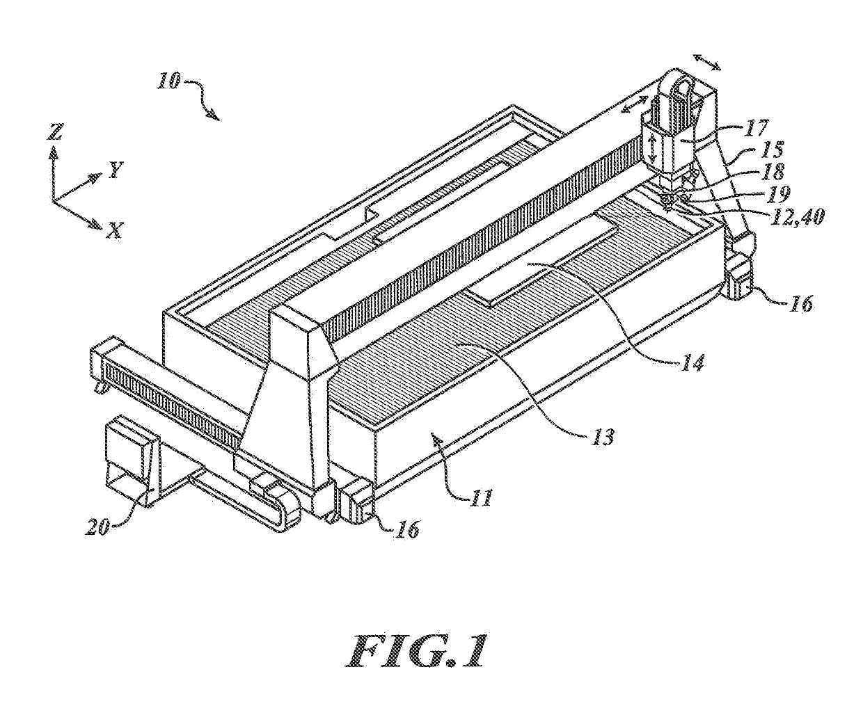
[0043]In the following description, certain specific details are set forth in order to provide a thorough understanding of various disclosed embodiments. However, one of ordinary skill in the relevant art will recognize that embodiments may be practiced without one or more of these specific details. In other instances, well-known structures associated with fluid jet cutting systems and methods of operating the same may not be shown or described in detail to avoid unnecessarily obscuring descriptions of the embodiments. For instance, well known control systems and drive components may be integrated into the fluid jet cutting systems to facilitate movement of the fluid jet cutting head assembly relative to the workpiece or work surface to be processed, or vice versa. These systems may include drive components to manipulate the cutting head about multiple rotational and / or translational axes, as is common in multi-axis manipulators of fluid jet cutting systems. Example fluid jet cuttin...


PUM

PropertyMeasurementUnit
Lengthaaaaaaaaaa
Lengthaaaaaaaaaa
Lengthaaaaaaaaaa

Abstract

Reinforced diamond nozzles and methods of making the same for fluid jet cutting applications are provided. An example method includes forming or providing a tubular diamond body having a jet passage extending therethrough and establishing a protective casing around the tubular diamond body so that an entirety or substantially an entirety of an outer circumferential surface area of the tubular diamond body is directly contacted and reinforced by the protective casing. Establishing the protective casing around the tubular diamond body may include thermal spraying, casting, direct metal laser sintering, or other fabrication techniques.

Description

CROSS-REFERENCE TO RELATED APPLICATION[0001]This application claims the benefit of Provisional Application No. 62 / 608,459, filed Dec. 20, 2017, the disclosure of which is incorporated herein by reference.BACKGROUNDTechnical Field[0002]This disclosure is related to fluid jet cutting systems and related components and methods, and, more particularly, to abrasive fluid jet nozzles and methods of making the same.Description of the Related Art[0003]Fluid jet cutting systems, such as waterjet or abrasive waterjet cutting systems, are used for cutting a wide variety of materials, including stone, glass, ceramics and metals. In a typical waterjet cutting system, high-pressure water flows through a cutting head having a nozzle which directs a cutting jet onto a workpiece after the jet is formed via an orifice unit. The system may draw or feed abrasive media into the high-pressure waterjet to form a high-pressure abrasive waterjet. In addition to such abrasive waterjet cutting systems, other ...

Claims


Application Information

Patent Timeline
IPC IPC(8): B24C5/04C23C16/27B24C1/04
CPCB24C5/04C23C16/27B24C1/045C23C16/01B23P15/00B23P11/025C23C4/06C23C4/16C23C4/08
Inventor HASHISH, MOHAMEDHOPKINS, JORDAN J.
Owner FLOW INT
Why Eureka
Try Eureka