
Multi-part injection-molded multi-chamber plastic tank having an oblique joining surface

Inactive Publication Date: 2019-06-20
ROCHLING AUTOMOTIVE SE
View PDF0 Cites 2 Cited by
  • Summary
  • Abstract
  • Description
  • Claims
  • Application Information

AI Technical Summary

Benefits of technology

The present invention aims to improve the manufacturing process of a multi-chamber plastic tank. This involves injection-molding engineering techniques to improve the overall manufacturability of the tank.

Problems solved by technology

The joining surface that is oblique with respect to the reference plane results, however, in surprisingly wide leeway in terms of the physical design of the multi-chamber plastic tank.

Method used


Image

  • Multi-part injection-molded multi-chamber plastic tank having an oblique joining surface
  • Multi-part injection-molded multi-chamber plastic tank having an oblique joining surface
  • Multi-part injection-molded multi-chamber plastic tank having an oblique joining surface

Examples


first embodiment

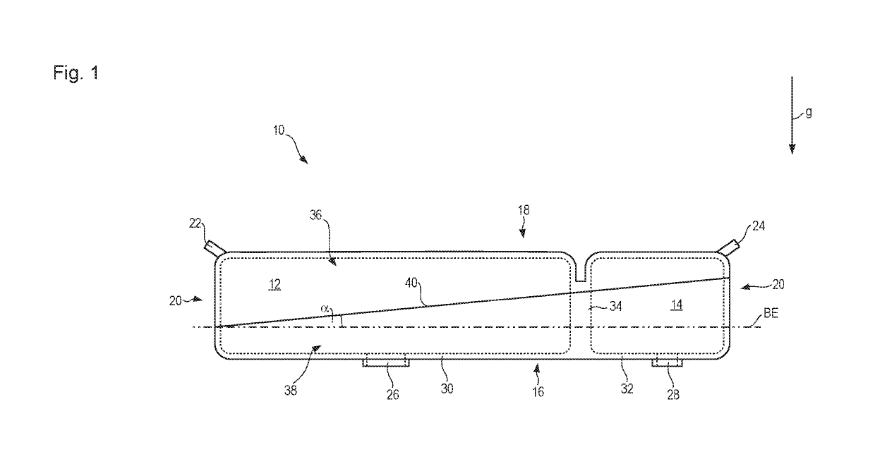
[0034]Referring now to the drawing wherein the showings are for the purpose of illustrating preferred and alternative embodiments of the invention only and not for the purpose of limiting the same, FIG. 1 shows a first embodiment according to the present invention of a multi-chamber plastic tank that is designated in general as 10. Multi-chamber plastic tank 10 encompasses a larger reservoir chamber 12 and, entirely fluid-mechanically separated therefrom, a smaller reservoir chamber 14. As the names indicate, reservoir chamber 12 has a greater capacity than reservoir chamber 14. In the example depicted, multi-chamber plastic tank 10 is intended for use in a motor vehicle, reservoir chamber 12 being embodied to receive, store, and deliver diesel fuel, and reservoir chamber 14 being embodied to receive, store, and deliver aqueous urea solution. The aqueous urea solution serves for exhaust emissions control in a manner known per se, so that oxides of nitrogen can be selectively reduced...

second embodiment

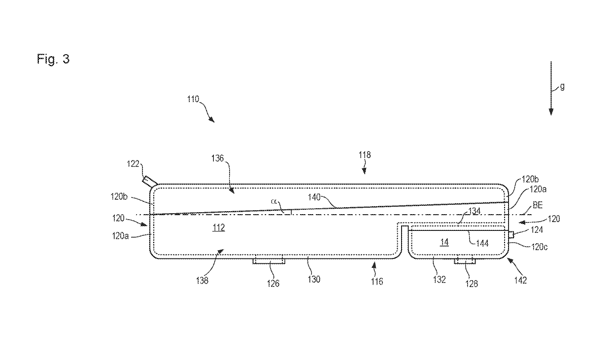
[0056]Because the smaller joining plane 144 is oriented parallel to reference plane BE in the second embodiment, the larger joining plane 140 encloses the same angle α with the smaller joining plane 144 as with reference plane BE. In a departure from what is depicted in FIG. 3, the smaller joining plane 144 can likewise enclose an angle with reference plane BE. That angle can be the same as or different from the angle α between the larger joining plane 140 and reference plane BE.

[0057]Plastic tank components 136, 138, and 142 are unmolded from their respective injection molding tools in unmolding directions that are oriented parallel to direction of gravity g. This assumes that the individual tank components 136, 138, and 142 are oriented, as depicted in FIG. 3, in their respective operationally ready installation position. A tank component of course can be, and is, generated in a spatial orientation that deviates from the subsequent installation position. The unmolding direction pa...


PUM

PropertyMeasurementUnit
Angleaaaaaaaaaa
Angleaaaaaaaaaa
Angleaaaaaaaaaa

Abstract

A multi-chamber plastic tank, in particular for a motor vehicle, encompasses at least two reservoir chambers, fluid-mechanically separated from one another, which are each mutually independently fillable with liquid and from each of which liquids stored therein are mutually independently non-mixingly withdrawable, the multi-chamber plastic tank including a plurality of injection-molded plastic tank components that are intermaterially connected to one another along a joining surface, provision is made that with regard to the final operationally ready installation position of the multi-chamber plastic tank, at least one joining surface is inclined, relative to a reference plane orthogonal to the direction of gravity, in such a way that it is neither parallel nor orthogonal to the reference plane.

Description

[0001]The present invention relates to a multi-chamber plastic tank, in particular for a motor vehicle, encompassing at least two reservoir chambers, fluid-mechanically separated from one another, which are each mutually independently fillable with liquid and from each of which liquids stored therein are mutually independently non-mixingly withdrawable, the multi-chamber plastic tank comprising a plurality of injection-molded plastic tank components that are intermaterially connected to one another along a joining surface.BACKGROUND OF THE INVENTION[0002]A multi-chamber plastic tank of this species is known from DE 10 2014 209 380 A1. With this multi-chamber plastic tank, which serves to store both diesel fuel and, separately therefrom, aqueous urea solution for selective catalytic reduction, the chamber receiving the urea solution is embodied as a protuberance of a tank component, which protuberance extends from a wall portion forming a bottom of the diesel reservoir chamber, into ...

Claims


Application Information

Patent Timeline
IPC IPC(8): B60K15/03B29D22/00
CPCB60K15/03177B29D22/003B60K2015/03493B60K2015/03032F01N2610/1406F01N3/2066F01N2610/02B60K2015/03118B60K13/04B60K15/03B29C65/48B29C66/301B29C65/02B29C65/08B29C66/54B29C66/1162B29C66/1142B29L2031/7172Y02A50/20Y02T10/12B29C65/00
Inventor NAGEL, THOMAS
Owner ROCHLING AUTOMOTIVE SE
Features
  • Generate Ideas
  • Intellectual Property
  • Life Sciences
  • Materials
  • Tech Scout
  • Unparalleled Data Quality
  • Higher Quality Content
  • 60% Fewer Hallucinations
Learn More