A power system for a marine vehicle, comprising a propulsion unit, a rudder bearing and fittings

a technology for marine vehicles and power systems, applied in bearings, roller bearings, shafts, etc., can solve the problems of rudder bearing position, drive unit mounting, and occurrence of leverage effect, so as to facilitate the delivery, mounting and dismounting of the power system on the marine vehicle, and reduce the leverage effect. , the effect of improving the hydrodynamic properties

Active Publication Date: 2019-06-20
GE ENERGY POWER CONVERSION TECH
View PDF3 Cites 0 Cited by
  • Summary
  • Abstract
  • Description
  • Claims
  • Application Information

AI Technical Summary

Benefits of technology

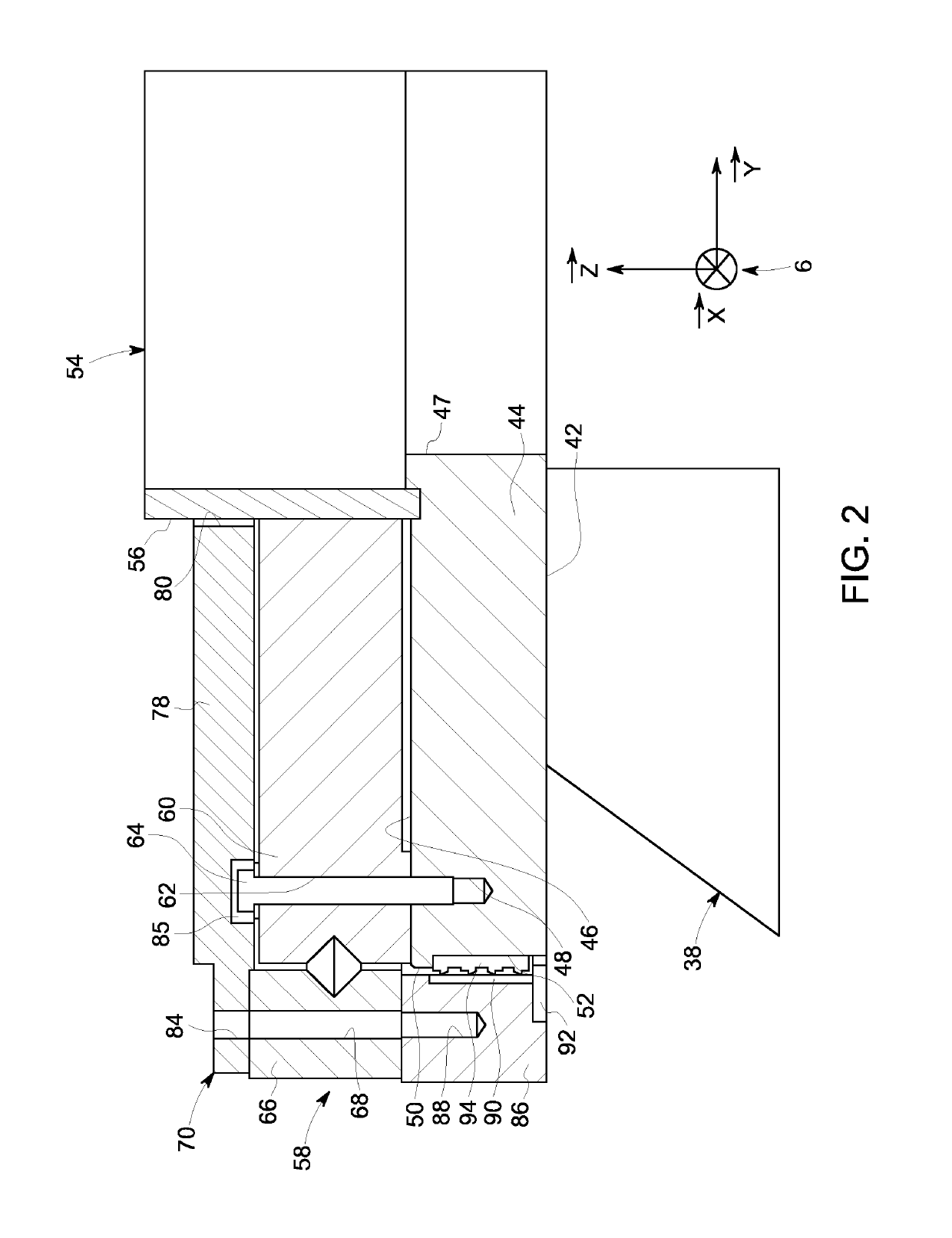
[0015]Such a power system, including both the mobile housing and the rudder bearing, is particularly compact. Therefore, the delivery, mounting and dismounting of the power system on a marine vehicle are facilitated. Furthermore, the rudder bearing can be oriented significantly parallel to a median plane of the hull element, and placed nearby. The result is better hydrodynamic properties and a reduction of the leverage effect that occurs while the drive unit undergoes movements following forces directed in a longitudinal or transverse direction compared to the marine vehicle.

Problems solved by technology

Among these disadvantages, the use of a direction cone results in the rudder bearing position which is relatively far from the sealing gaskets.
It leads to the occurrence of a leverage effect when the drive unit is shifting slightly in the vertical plane, when forces are applied to the lower part of the propulsion unit.
On the other hand, another disadvantage is that the hull element on which the drive unit is mounted is often directed according to an inclined plane as compared to the horizontal plane of the vehicle.
However, this solution is very expensive both in terms of design as well as manufacturing costs.
However, this kind of solution still has some disadvantages, because this adaptation part has an additional hydrodynamic resistance and generates further costs related to manufacturing.

Method used


Image

  • A power system for a marine vehicle, comprising a propulsion unit, a rudder bearing and fittings
  • A power system for a marine vehicle, comprising a propulsion unit, a rudder bearing and fittings
  • A power system for a marine vehicle, comprising a propulsion unit, a rudder bearing and fittings

Examples


Embodiment Construction

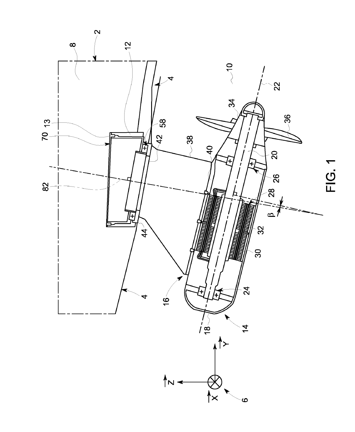
[0031]With reference to FIG. 1, it represents the stern 4 of a ship 2. A system of vectors 6 is defined relative to the ship 2. The system 6 consists of three orthogonal vectors, and. The vector is perpendicular to the plane of FIG. 1 and led by the pitch axis of the ship 2, while ship 2 is arranged according to a normal operating plane. A normal operation plane is the one containing longitudinal and transverse directions of the ship 2, while the latter moves on a calm sea and under normal loading conditions. The vector is horizontal relative to the plane of FIG. 1 and oriented according to the roll axis of the ship 2, while the ship 2 is arranged according to a normal operating plane. The vector is vertical relative to FIG. 1 and oriented according to the yaw axis of the ship 2, while the ship 2 is arranged according to a normal operating plane. Also as defined by FIG. 1, compared with the hull element 4, an inner part 8 and an outer part 10.

[0032]The hull element 4 has a bore lead...


PUM


Abstract

This power system for mounting on a marine vehicle includes a propulsion unit, means for securing the propulsion assembly to a hull element of the vehicle and a rudder bearing mechanically connecting the propulsion unit with the fittings. The fittings are configured so that once the power system is mounted on the hull element; the plane of the rudder bearing is inclined relative to a plane containing one longitudinal axis and one transverse axis of the marine vehicle.

Description

BACKGROUND OF THE DISCLOSURE[0001]This invention concerns propulsion units of marine vehicles, such as ships, submarines or even oil platforms.[0002]These propulsion units, also known by the name “propulsion-oriented drive”, or “POD”, generally include a mobile housing mounted with a pivot link to a hull element of the marine vehicle. For example, the hull element may be placed at the stern or prow of a ship.[0003]In order to provide the pivot link between the mobile housing and the hull element, a rudder rotating bearing can be mounted inside and attached to the hull element.[0004]During the drive unit installation, a direction cone is installed from the inside of the hull element. The upper end of the direction cone is fastened on the rudder bearing. The mobile housing is afterwards introduced from the outside of the hull element, so that its upper end is connected to the lower end of the direction cone. Then, the upper end of the mobile housing is connected to the lower end of th...

Claims


Application Information

Patent Timeline
Patent Type & Authority Applications(United States)
IPC IPC(8): B63H5/125F16C19/10F16C19/30F16C35/04
CPCB63H5/125F16C19/10F16C19/30F16C35/042B63H2005/1258F16C2300/14F16C2326/30B63H5/1252
Inventor JULLIAND, LIONELDESCHAMPS, THIERRYBARTH, LAURENT
Owner GE ENERGY POWER CONVERSION TECH
Why Eureka
Try Eureka