Light Emitting Diode Photobioreactors And Methods Of Use

a light-emitting diode and photobioreactor technology, applied in the field of bioreactor systems, can solve the problems of limited scaling up, limited led lighting, and insufficient teaching or suggesting of photosynthetic organisms, so as to maximize homogeneous light distribution, limit contamination, and ensure the effect of turbulen

Active Publication Date: 2019-06-20
AVESPA CORP
View PDF0 Cites 1 Cited by
  • Summary
  • Abstract
  • Description
  • Claims
  • Application Information

AI Technical Summary

Benefits of technology

[0026]In an embodiment, the invention may be formed as a group of reactor vessels in fluidic engagement with at least one vessel for replacement media (designated a firewall vessel) and at least one harvest tank vessel. Sufficient valving is provided to enable isolation of the individual vessels and to alternatively and individually bring them into fluidic engagement with at least one firewall and at least one harvest vessel, as needed. All connective hardware can be readily rinsed, sterilized and flushed in order to limit contamination. The bottom of the reactor vessel contains at least one bubbler connected to a source of air sufficient to operate the bubbler in which bubbles produce currents, which circulate the medium and microalgae. Optionally, the vessel contains a second bubbler for the introduction of gasses such as CO2 (carbon dioxide) into the medium. Lights comprising thin and substantially flat light guides powered by LEDs are arranged vertically in the vessel, preferably in arrays to maximize homogeneous light distribution yet providing sufficient turbulence in order to maximize algal biomass suspension, exposure to light, and oxygen venting.
[0027]In an embodiment, the invention teaches a method of culturing microalgae in which the reactor vessels are filled with medium and a starter microalgae solution and exposed to sufficient light to allow the microalgae to grow at a rate such that they may be harvested in a semi-continuous manner, thereby ensuring that a given percentage of the algal biomass is drained and harvested every day and replaced by the same amount of nutrient rich medium in the most efficient possible way.
[0029]In an embodiment, the bioreactor designs of the present invention allow for harvesting from about 10% to about 50% of the bioreactor vessel each day allowing harvesting of the full vessel every 2-10 days. The harvested biomass is generally at a density of three to ten times based on dry weight that of conventional systems. As such the present invention can achieve efficiencies as great as 100 times that of conventional systems by not only producing higher biomass concentration with a higher energetic efficiency but also by harvesting more often when compared to a batch growth methodology.

Problems solved by technology

In this reference, the LED lighting is external and limited; scaling up appears to be limited.
These prior art methods and systems for the cultivation of photosynthetic organisms do not teach or suggest the elements necessary for providing optimal conditions for the growth and harvesting of photosynthetic organisms, such as microalgae, and do not appear to be scalable for commercial operations.

Method used


Image

  • Light Emitting Diode Photobioreactors And Methods Of Use
  • Light Emitting Diode Photobioreactors And Methods Of Use
  • Light Emitting Diode Photobioreactors And Methods Of Use

Examples


examples

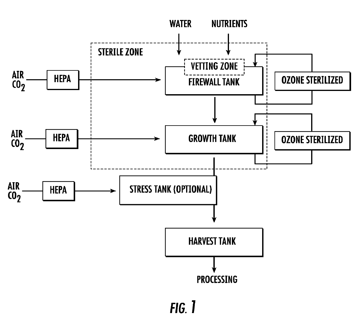
[0126]Algal Biomass Process Control Protocols and Parameters

[0127]Each type of bioreactor, alga strain, and end usage for the algae require specific methods and standard operating protocols to be tailored and optimized. The following protocols intend to provide an overall understanding of the process and key steps necessary to run a tank-based photo-bioreactor in accordance with the present invention.

[0128]The construction and arrangement of the working environment has been designed to limit, to the utmost extent possible, any external contaminations, therefore good manufacturing practices (GMPs) and clean room operation (HEPA filtered, operator wearing protective equipment) are used as many water and airborne parasites can interfere and contaminate algae being grown for considerable amount of time in a semi-continuous method unlike a batch system.

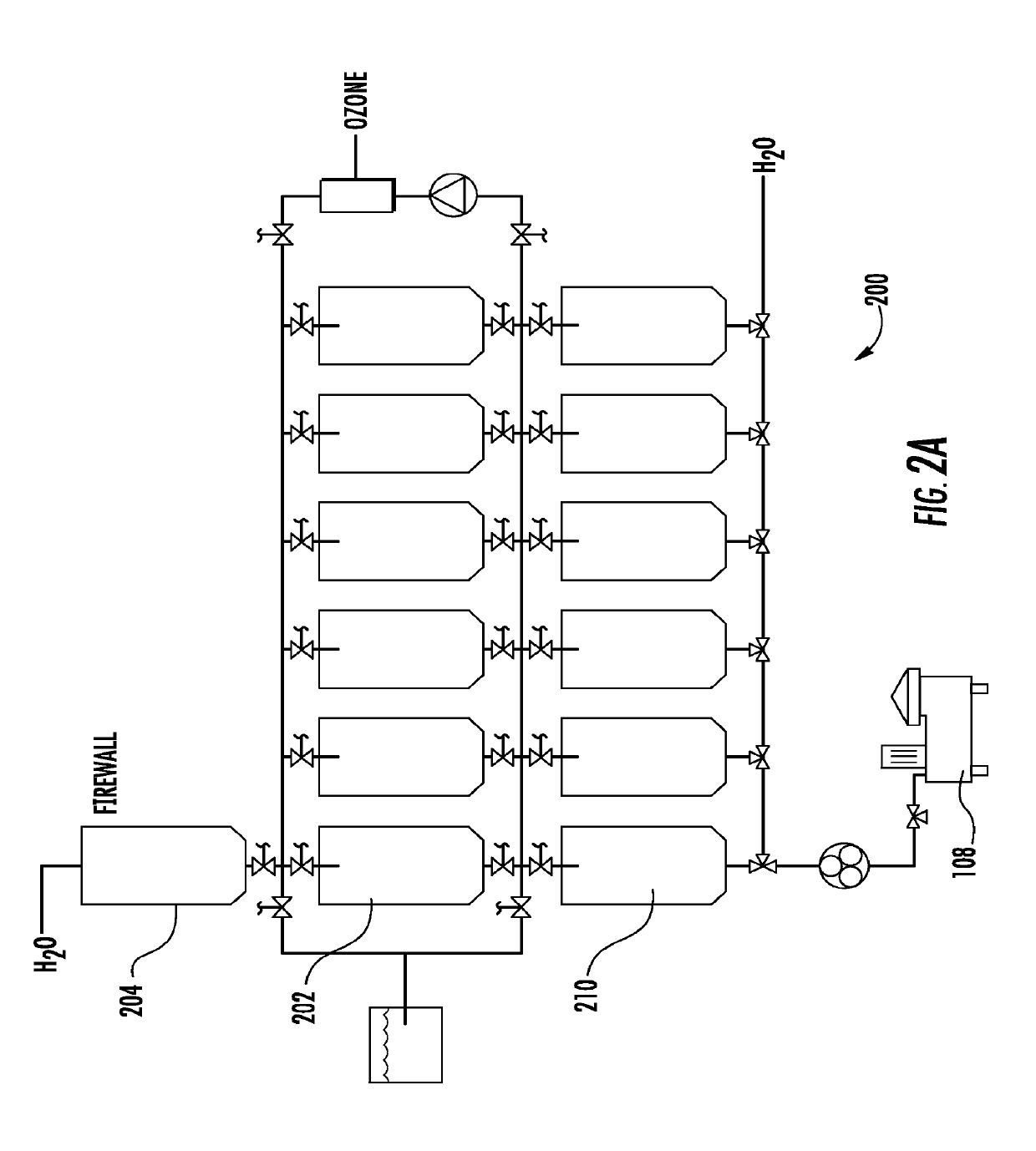
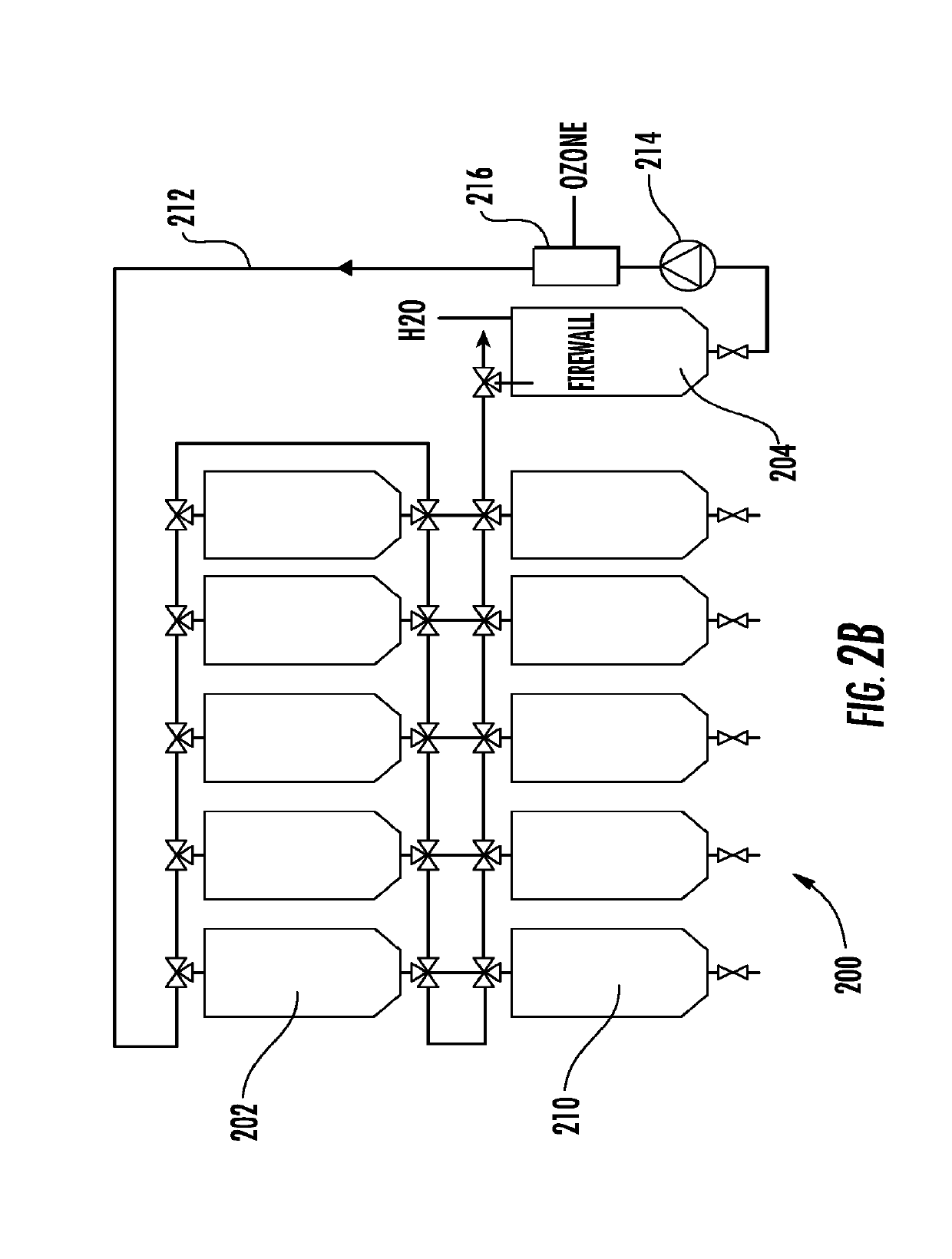
[0129]Growth Phase: Cylindrical and IBC Tanks

[0130]Morning Setup as an Operator would Walk in:

[0131]Firewall tank is already filled with ...


PUM

PropertyMeasurementUnit
wavelengthsaaaaaaaaaa
densityaaaaaaaaaa
densityaaaaaaaaaa

Abstract

A photobioreactor system and a process for its use is illustrated, whereby water and nutrients from multiple sources are balanced (mixed using aeration) to the specific requirements of the particular photosynthetic organism strain used, sterilized, further mixed to balance the system and seeded with the photosynthetic microorganism, e.g. microalgae (dilution of a concentrated stock or added to an existing algal biomass). In accordance with such an embodiment, the algal biomass is then grown for a most efficient number of hours in a totally controlled environment where temperature (using aeration, an internal coil cooling system, or a combination thereof), pH (via CO2 delivery) and light delivery (using internal lighting directly inside the algal biomass) are optimized to the algal strain grown.

Description

CROSS REFERENCE TO RELATED APPLICATIONS[0001]This patent application is a divisional of now-allowed U.S. patent application Ser. No. 15 / 416,989 (filed Jan. 26, 2017), which is a continuation-in-part of PCT / US2016 / 044796 (filed Jul. 29, 2016), which claims priority to U.S. Provisional Patent Application No. 62 / 198,652 (filed Jul. 29, 2015), the entirety of each of which applications is incorporated by reference herein in its entirety for any and all purposes.FIELD OF THE INVENTION[0002]The present invention is directed toward a bioreactor system for optimizing the cultivation and harvesting of photosynthetic organisms. The invention particularly relates to bioreactor systems which are essentially self-contained modular scalable units that maintain all critical parameters, such as the levels of carbon dioxide, oxygen, water, nutrients, temperature, biomass suspension and light energy necessary for the optimal preparation, growth and harvesting of such photosynthetic organisms. The inv...

Claims


Application Information

Patent Timeline
Patent Type & Authority Applications(United States)
IPC IPC(8): C12M1/00F21V8/00C12M1/02C12M1/12
CPCC12M21/02G02B6/0085G02B6/0078G02B6/0068C12M29/06C12M27/00C12M31/10C12M29/26C12M37/00C12N1/12
Inventor PUNCHARD, DAVIDBOIS, PHILIPPECORTINA BURGUENO, ANGELA
Owner AVESPA CORP
Why Eureka
Try Eureka