Monitoring a hydrodynamic clutch
a hydrodynamic clutch and monitoring technology, applied in the direction of fluid couplings, gearings, couplings, etc., can solve the problem that the temperature parameter of an operational condition of a hydrodynamic clutch is often insufficient for a determination of efficiency or stability
- Summary
- Abstract
- Description
- Claims
- Application Information
AI Technical Summary
Benefits of technology
Problems solved by technology
Method used
Image
Examples
Embodiment Construction
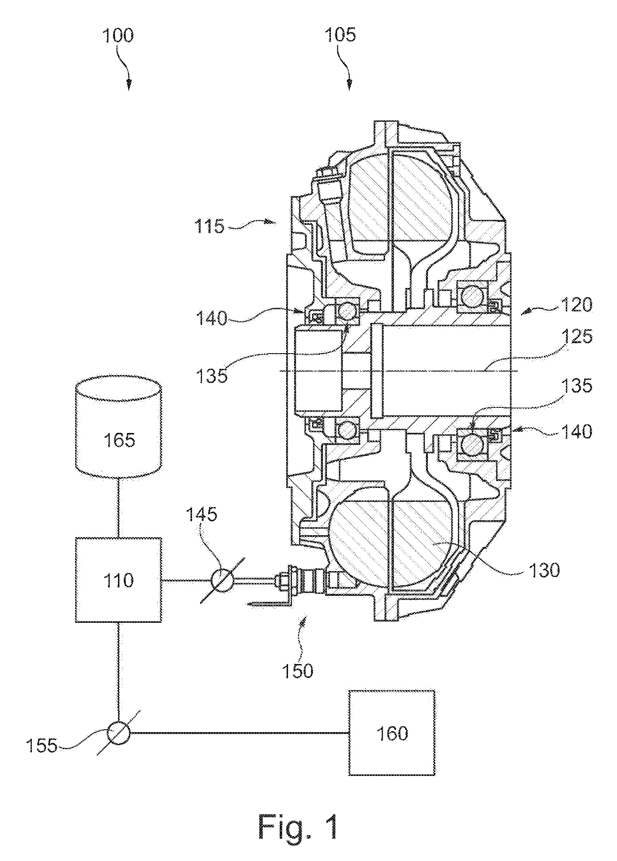
[0028]Referring now to the drawings, and more particularly to FIG. 1, there is shown a clutch system 100 having a hydrodynamic clutch 105 and a control unit 110. Clutch 105 has an input side 115 and an output side 120 which together are rotatably mounted around a common axis of rotation 125. A hydraulic fluid 130 produces a torque coupling between input side 115 and output side 120. Input side 115 is mounted opposite to output side 120 with at least one antifriction bearing 135. Depending upon a clutch type, the connections for introduction and termination of torque loads on the antifriction bearings 135 can vary, even if their arrangement is unchanged. One or more seals 140, which can include various materials, can be provided between input side 115 and output side 120.
[0029]Clutch 105 may be available in one or several predefined embodiments. Clutch system 100 can for example be used with clutches 105 having different, predetermined diameters in a range of approximately 154 to 115...
PUM
 Abstract
Description
Claims
Application Information
 - R&D
- Intellectual Property
- Life Sciences
- Materials
- Tech Scout
- Unparalleled Data Quality
- Higher Quality Content
- 60% Fewer Hallucinations
Browse by: Latest US Patents, China's latest patents, Technical Efficacy Thesaurus, Application Domain, Technology Topic, Popular Technical Reports.
© 2025 PatSnap. All rights reserved.Legal|Privacy policy|Modern Slavery Act Transparency Statement|Sitemap|About US| Contact US: help@patsnap.com


