Inductor component and power supply module

a technology of power supply module and component, which is applied in the direction of transformer/inductance magnetic core, inductance, and printed circuit non-printed electric components association, etc. it can solve the problems that the module using a plurality of inductor components may not be able to achieve the required characteristics, and the configuration described above may not provide satisfactory characteristics, etc. problems, to achieve the effect of reducing the planar area of the power supply module, reducing variation among inductor components, and improving characteristics

Active Publication Date: 2019-06-20
MURATA MFG CO LTD
View PDF0 Cites 3 Cited by
  • Summary
  • Abstract
  • Description
  • Claims
  • Application Information

AI Technical Summary

Benefits of technology

[0019]This configuration reduces the planar area of the power supply module.
[0020]Preferred embodiments of the present invention reduce variation among inductor components, improve characteristics such as DCR, and reduce characteristic variation between a plurality of inductors.

Problems solved by technology

Because of the sophistication of electronic devices in recent years, the inductor component with the configuration described above may not be able to provide satisfactory characteristics.
In this case, due to characteristic variation among inductor components, a module which uses a plurality of inductor components may not be able to achieve required characteristics.

Method used


Image

  • Inductor component and power supply module
  • Inductor component and power supply module
  • Inductor component and power supply module

Examples


Embodiment Construction

[0031]Inductor components according to preferred embodiments of the present invention will be described with reference to the drawings.

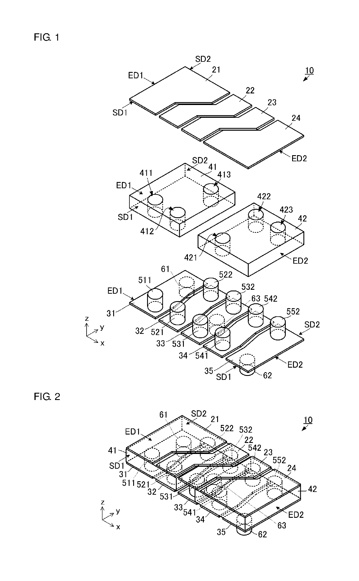
[0032]An inductor component according to a first preferred embodiment of the present invention will be described with reference to the drawings. FIG. 1 is an exploded perspective view of the inductor component according to the first preferred embodiment of the present invention. FIG. 2 is an external perspective view of the inductor component according to the first preferred embodiment of the present invention.

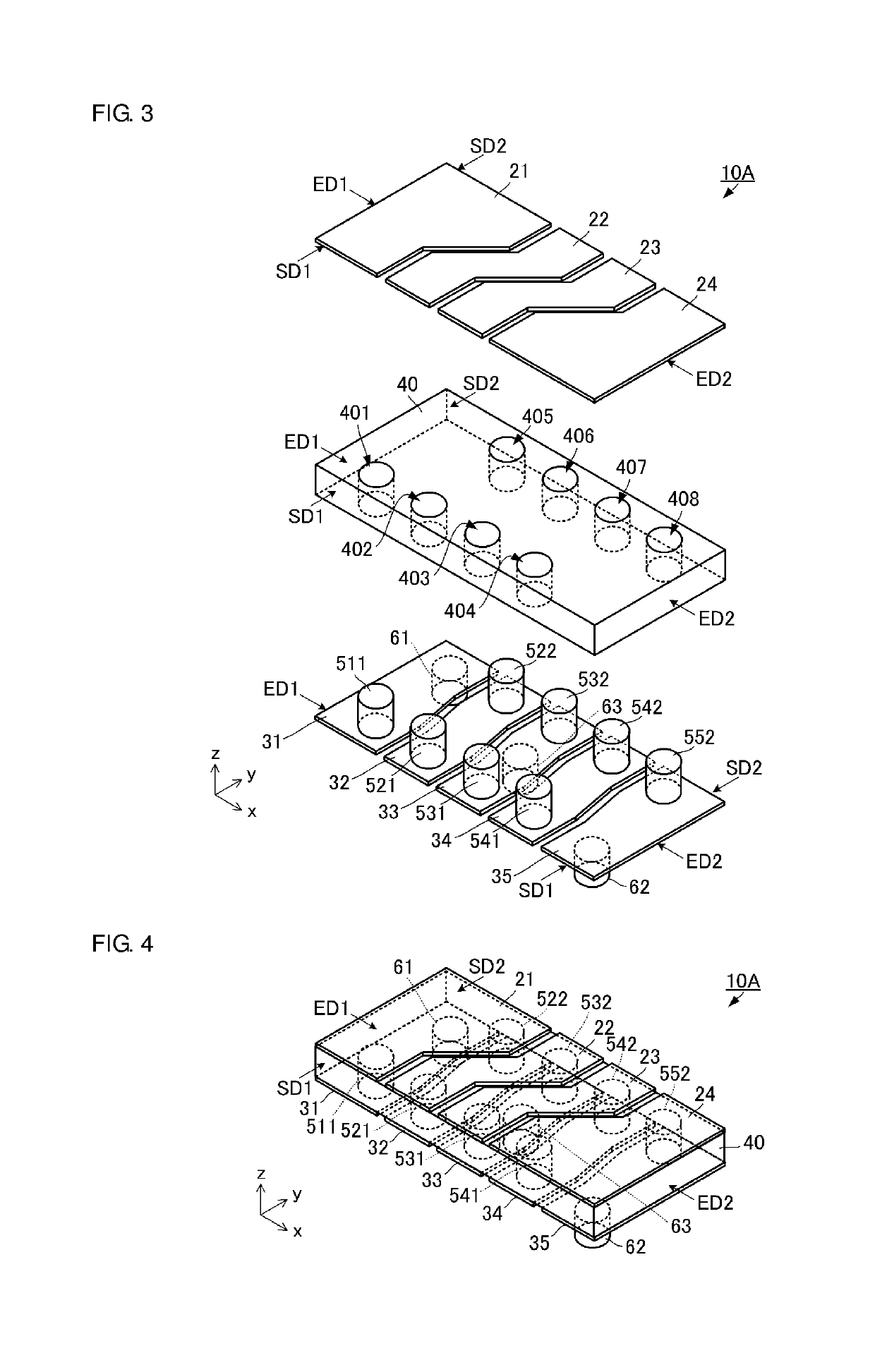
[0033]As illustrated in FIGS. 1 and 2, an inductor component 10 includes first metal plates 21, 22, 23, and 24, second metal plates 31, 32, 33, 34, and 35, cores 41 and 42, metal pins 511, 521, 522, 531, 532, 541, 542, and 552, and terminal electrodes 61, 62, and 63.

[0034]The cores 41 and 42 have a rectangular or substantially rectangular parallelepiped shape including upper and lower surfaces. The cores 41 and 42 are preferably, for example, r...


PUM

PropertyMeasurementUnit
thicknessaaaaaaaaaa
shapeaaaaaaaaaa
helical shapeaaaaaaaaaa

Abstract

An inductor component includes cores, a coil disposed in the cores, and terminal electrodes. The coil includes first metal plates disposed on an upper surface of the cores, second metal plates disposed on a lower surface of the cores, and a plurality of metal pins each passing through one of the cores in a thickness direction. The coil has a helical shape by connecting the first metal plates to the second metal plates, with the plurality of metal pins therebetween. The terminal electrodes are spaced apart along a direction in which the helical shape extends, and are connected to the coil.

Description

CROSS REFERENCE TO RELATED APPLICATIONS[0001]This application claims the benefit of priority to Japanese Patent Application No. 2016-171464 filed on Sep. 2, 2016 and is a Continuation Application of PCT Application No. PCT / JP2017 / 030482 filed on Aug. 25, 2017. The entire contents of each of the above-identified applications are hereby incorporated herein by reference.BACKGROUND OF THE INVENTION1. Field of the Invention[0002]The present invention relates to an inductor component including a plurality of inductors, and a power supply module including the inductor component.2. Description of the Related Art[0003]Various types of inductor components are currently used. For example, an inductor component disclosed in Japanese Unexamined Patent Application Publication No. 2000-40620 includes a core substrate and a coil. The core substrate is formed, for example, by a printed circuit board. The coil is formed by a conductor and includes an upper-side wiring pattern, a lower-side wiring pat...

Claims


Application Information

Patent Timeline
Patent Type & Authority Applications(United States)
IPC IPC(8): H01F27/28H05K1/18H01F27/24H01F27/29H02M7/00
CPCH01F27/2804H05K1/181H01F27/24H01F27/29H02M7/003H05K2201/1003H05K2201/10053H02M3/335H01F2027/2809H01F17/0013H01F17/0033H01F2017/002H01F2027/297H02M3/158H02M3/155H01F37/00H05K1/18H02M3/28H01F17/04H01F17/00
Inventor MIYASHITA, MUNETAKETANGE, TAKAYUKIHASHI, HIDEAKI
Owner MURATA MFG CO LTD
Why Eureka
Try Eureka