Unlock instant, AI-driven research and patent intelligence for your innovation.

Vehicle control system

a technology of vehicle control and control system, applied in the field of vehicle control system, can solve problems such as erroneous determination and interruption of follow-up control

Active Publication Date: 2019-06-27
TOYOTA JIDOSHA KK +1
View PDF3 Cites 3 Cited by
  • Summary
  • Abstract
  • Description
  • Claims
  • Application Information

AI Technical Summary

Benefits of technology

The patent describes a system that can determine when a vehicle should stop following a target path or when it is approaching its maximum allowed deviation. The system uses a method to determine if the vehicle's behavior is within an acceptable range, based on the speed and position of the vehicle when it reaches the target path. This allows for more accurate control of the vehicle's behavior and improves the overall efficiency and safety of the system.

Problems solved by technology

When the method described above is used, even though staggering of the vehicle behavior is actually forced to be converged with the continuation of the path-following control, determination is made that there is a possibility of lane departure, and erroneous determination may be made that the path-following control should be interrupted.

Method used


Image

  • Vehicle control system
  • Vehicle control system
  • Vehicle control system

Examples


embodiment 1

[0034]Embodiment 1 of the disclosure will be described referring to FIGS. 1 to 12B.

1. Configuration Example of Vehicle Control System

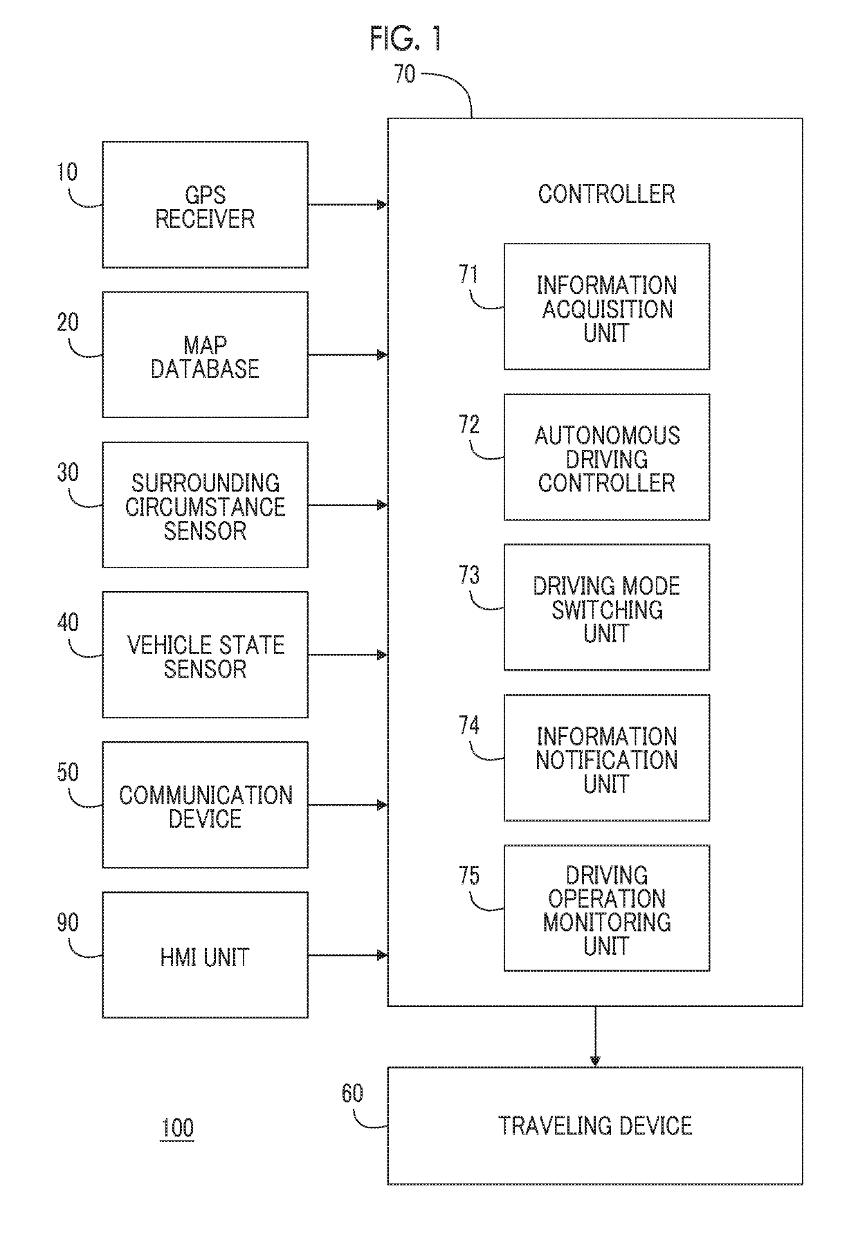
[0035]FIG. 1 is a block diagram showing a configuration example of a vehicle control system 100 according to Embodiment 1 of the disclosure. The vehicle control system 100 according to Embodiment 1 is an autonomous driving system that is mounted in a vehicle 1 (see FIG. 4) and controls autonomous driving of the vehicle 1. In more detail, the vehicle 1 has, as a driving mode, a manual driving mode and an autonomous driving mode. In the manual driving mode, a driver becomes a subject of driving of the vehicle 1 and an operation of the vehicle 1 is performed. In the autonomous driving mode, the vehicle control system 100 becomes a subject of driving of the vehicle 1.

[0036]The vehicle control system 100 includes a global positioning system (GPS) receiver 10, a map database 20, a surrounding circumstance sensor 30, a vehicle state sensor 40, a communication...

embodiment 2

1. Outline of Embodiment 2

[0110]Embodiment 2 is different from Embodiment 1 in system limit determination processing for determining whether or not the path-following control is to be continued. Specifically, in the system limit determination processing of Embodiment 2, in order to determine whether or not the behavior of the vehicle 1 is within the system limit, a speed range RΔEd that is defined by the maximum value (=ALMT×2πfLMT) and the minimum value (=−ALMT×2πfLMT) of the cosine function corresponding to a function of a gradient of the allowable limit sine wave is used instead of the ellipse shown in FIG. 6.

[0111]In addition, with the system limit determination processing according to Embodiment 2, determination is made whether or not the lateral deviation speed ΔEd of the vehicle 1 when the vehicle 1 intersects the target path TP (that is, when the lateral deviation Ed is zero) falls within the speed range RΔEd. Then, when the lateral deviation speed ΔEd when the vehicle 1 int...


PUM


Abstract

A vehicle control system that executes path-following control includes a controller. The vehicle control system is configured to determine whether or not the path-following control is to be continued based on whether or not a coordinate point with current lateral deviation speed and lateral deviation as an X coordinate and a Y coordinate, respectively, falls within an ellipse to be specified on an X-Y plane with a time as a parameter, a value of a cosine function to be obtained by time-differentiating a function of an allowable limit sine wave on an X axis, and a value of the function of the allowable limit sine wave on a Y axis.

Description

INCORPORATION BY REFERENCE[0001]The disclosure of Japanese Patent Application No. 2017-248175 filed on Dec. 25, 2017 including the specification, drawings and abstract is incorporated herein by reference in its entirety.BACKGROUND1. Technical Field[0002]The present disclosure relates to a vehicle control system, and in particular, to a vehicle control system that executes path-following control for controlling traveling of a vehicle to follow a target path.2. Description of Related Art[0003]Japanese Unexamined Patent Application Publication No. 2004-168192 (JP 2004-168192 A) discloses a lane departure prevention device. In the lane departure prevention device, a future lateral displacement is estimated using a yaw angle of a host vehicle with respect to a traveling lane, a lateral displacement (lateral deviation) from the center of the traveling lane, a curvature of the traveling lane, and a vehicle speed. Then, when the estimated lateral displacement (estimated deviation value) is ...

Claims


Application Information

Patent Timeline
IPC IPC(8): B60W30/12B60W50/14G08G1/16B62D1/28
CPCB60W30/12B60W50/14G08G1/167B62D1/286B60W2050/143B60W2540/18B60W30/10B62D15/025B60W2050/146B60W2554/00B60W2556/50B60W60/00
Inventor IRIE, RYOAMANO, MASATERUAKATSUKA, HISAYA
Owner TOYOTA JIDOSHA KK
Features
  • R&D
  • Intellectual Property
  • Life Sciences
  • Materials
  • Tech Scout
  • Unparalleled Data Quality
  • Higher Quality Content
  • 60% Fewer Hallucinations
Learn More