Power conversion system

a power conversion system and power conversion technology, applied in the direction of electric variable regulation, process and machine control, instruments, etc., can solve the problems of power conversion efficiency decline, and achieve the effect of reducing the power loss caused by switching

Active Publication Date: 2019-07-04
PANASONIC INTELLECTUAL PROPERTY MANAGEMENT CO LTD
View PDF0 Cites 9 Cited by
  • Summary
  • Abstract
  • Description
  • Claims
  • Application Information

AI Technical Summary

Benefits of technology

[0007]It is therefore an object of the present disclosure to provide a power co

Problems solved by technology

In such a DC/AC converter, the power loss caused by switching of a switching ele

Method used


Image

  • Power conversion system
  • Power conversion system
  • Power conversion system

Examples


first embodiment

(2) First Embodiment

[0040]A power conversion system (power converter) according to a first embodiment will be described.

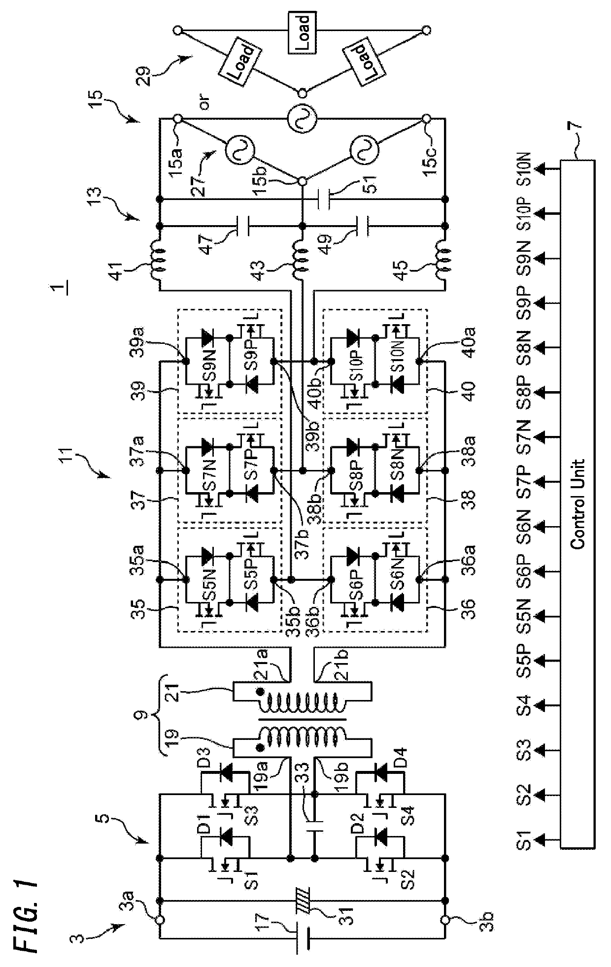
[0041]If an inverter circuit arranged on the primary side of the power converter is implemented to have a full-bridge configuration, the voltage output from the secondary side of the power converter is allowed to have its amplitude controlled by controlling the timings to turn ON and OFF the four switching elements thereof. In that case, however, in a period during which no power is output from the secondary side of the power converter, a circulating current is generated in the inverter circuit to cause loss of the power. Thus, the present inventors conceived a configuration for preventing a circulating current from being generated in the inverter circuit on the primary side as a main idea of the present disclosure.

[0042](2.1) Overview

[0043]As shown in FIG. 1, a power conversion system (power converter) 1 according to an aspect of the present disclosure includes a ...

second embodiment

(3) Second Embodiment

[0175]Turning all of the bidirectional switch units OFF when the cycloconverter is deactivated (i.e., when its output is stopped) could apply excessive stress to the bidirectional switch units due to loss of current flowing paths. A power conversion system according to a second embodiment is configured to reduce the stress applied to the bidirectional switch units when the output is stopped.

[0176](3.1) Overview

[0177]A power conversion system 1A according to a second embodiment will be described with reference to FIG. 20.

[0178]A power conversion system 1A includes a first set of connection terminals T11 and T12 and a second set of connection terminals T21, T22, and T23. The power conversion system 1A further includes an inverter circuit 110, a primary winding 121, a secondary winding 122, a converter circuit 130, reactors (AC reactors) L11-L13, and a control circuit 140. A DC power supply 200 such as a storage battery is connected as a first connection target to ...


PUM


Abstract

A control unit controls an inverter circuit such that a positive voltage and a negative voltage are alternately applied to a primary winding. The control unit controls a cycloconverter so as to allow no power to be transmitted between the cycloconverter and the inverter circuit in a first period including an inversion period during which a voltage of the primary winding has its polarity inverted. The control unit also controls the cycloconverter so as to allow power to be transmitted either in a first direction from the cycloconverter toward the inverter circuit, or in a second direction opposite from the first direction, in a second period different from the first period.

Description

TECHNICAL FIELD[0001]The present disclose relates to a power conversion system, and more particularly relates to a power conversion system configured to transmit power either unidirectionally or bidirectionally.BACKGROUND ART[0002]A power conversion system for transmitting power bidirectionally between a DC power supply and a device has recently been proposed (see, for example, Patent Literature 1).[0003]Patent Literature 1 discloses a DC / AC converter including an inverter unit, an RF transformer, a cycloconverter unit, and an AC filter.[0004]In this DC / AC converter, the inverter unit alternately applies a positive voltage and a negative voltage to a primary winding of the RF transformer. Then, the cycloconverter converts RF power, input via the RF transformer, into power with a commercial frequency and outputs AC power with the commercial frequency.[0005]In such a DC / AC converter, the power loss caused by switching of a switching element (bidirectional switch unit) causes a decline...

Claims


Application Information

Patent Timeline
IPC IPC(8): H02M3/335H02M1/42H01F38/14
CPCH02M3/33584H02M1/42H01F38/14H02M5/297H02M7/797H02M1/0054Y02B70/10H02M5/293H02M1/0058
Inventor NORISADA, TAKAAKIAKAMATSU, KEIJIKUSAMA, FUMITOYAMADA, GOKAMON, YUTAKAOZONE, MAKOTO
Owner PANASONIC INTELLECTUAL PROPERTY MANAGEMENT CO LTD
Why Eureka
Try Eureka