Bearingless implantable blood pump

Active Publication Date: 2019-07-11
TC1 LLC
View PDF0 Cites 6 Cited by
  • Summary
  • Abstract
  • Description
  • Claims
  • Application Information

AI Technical Summary

Benefits of technology

[0014]In another aspect, a second implantable blood pump includes a housing and a rotary motor. The housing defines an inlet opening, an outlet opening, and a dividing wall defining a blood flow conduit extending from the inlet opening to the outlet opening. The rotary motor includes a stator, hall effect sensors, and a rotor. The stator includes a stator core and stator coils. The stator core includes a toroidal portion. Each of the stator coils extends around one of separated segments of the toroidal portion. The stator is disposed within the housing circumferentially about the dividing wall such that the blood flow conduit extends through the stator core. The stator core is disposed circumferentially around at least a portion of the rotor. Each of the hall effect sensors is disposed in a respective gap between an adjacent pair of the stator coils. The rotor has a rotor axis of rotation and includes a

Problems solved by technology

People with heart failure often have shortness of breath and fatigue.
Years of living with blocked arteries and/or high bloo

Method used


Image

  • Bearingless implantable blood pump
  • Bearingless implantable blood pump
  • Bearingless implantable blood pump

Examples


Embodiment Construction

[0038]In the following description, various embodiments of the present invention will be described. For purposes of explanation, specific configurations and details are set forth in order to provide a thorough understanding of the embodiments. However, it will also be apparent to one skilled in the art that the present invention may be practiced without the specific details. Furthermore, well-known features may be omitted or simplified in order not to obscure the embodiment being described.

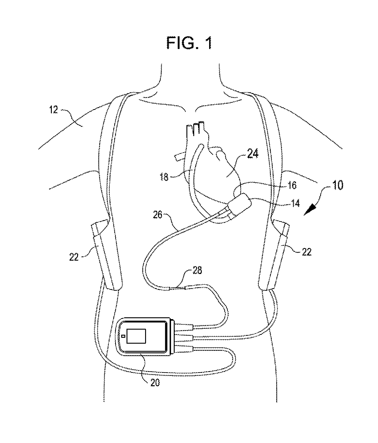
[0039]Referring now to the drawings, in which like reference numerals represent like parts throughout the several views, FIG. 1 shows a mechanical circulatory support system 10 implanted in a patient's body 12. The mechanical circulatory support system 10 includes an implantable blood pump assembly 14, a ventricular cuff 16, an outflow cannula 18, an external system controller 20, and power sources 22. The implantable blood pump assembly 14 can include a VAD that is attached to an apex of the left...


PUM


Abstract

Implantable blood pumps and related methods employ a compact rotary motor. The compact rotary motor includes a stator and a rotor. The stator includes a stator core and stator coils. The stator core includes a toroidal portion. Each of the stator coils extends around a respective segment of the toroidal portion. The stator being disposed within the housing circumferentially about the dividing wall such that the blood flow conduit extends through the stator core. The stator core is disposed circumferentially around at least a portion of the rotor.

Description

CROSS REFERENCE TO RELATED APPLICATIONS[0001]The present application claims the benefit of U.S. Provisional Patent Appln. No. 62 / 615,708 filed Jan. 10, 2018, entitled “BEARINGLESS IMPLANTABLE BLOOD PUMP; the full disclosure which is incorporated herein by reference in its entirety for all purposes.BACKGROUND[0002]Ventricular assist devices, known as VADs, often include an implantable blood pump and are used for both short-term (i.e., days, months) and long-term applications (i.e., years or a lifetime) where a patient's heart is incapable of providing adequate circulation, commonly referred to as heart failure or congestive heart failure. According to the American Heart Association, more than five million Americans are living with heart failure, with about 670,000 new cases diagnosed every year. People with heart failure often have shortness of breath and fatigue. Years of living with blocked arteries and / or high blood pressure can leave a heart too weak to pump enough blood to the b...

Claims


Application Information

Patent Timeline
IPC IPC(8): A61M1/10A61M1/12A61M60/178A61M60/216A61M60/422A61M60/538A61M60/81A61M60/82A61M60/857
CPCA61M1/1012A61M1/1029A61M1/122A61M1/1086A61M60/422A61M60/857A61M60/81A61M60/178A61M60/538A61M60/232A61M60/148A61M60/216
Inventor NYIKOS, THOMASWARBERGER, BERNHARD
Owner TC1 LLC
Why Eureka
Try Eureka