Blood treatment machine comprising a hollow fiber filter module for horizontal arrangement as well as hollow fiber filter module and use thereof

a blood treatment machine and filter module technology, applied in membrane technology, dialysis, membranes, etc., can solve the problems of not being able to adapt/variate in their position, partially showing considerable problems, and draining the solution (for example after priming) cannot be carried out without any additional expenditure, and achieves high efficiency, reduced drawbacks, and high degree of compactness and flexibility.

Active Publication Date: 2019-07-11
B BRAUN AVITUM
View PDF3 Cites 1 Cited by
  • Summary
  • Abstract
  • Description
  • Claims
  • Application Information

AI Technical Summary

Benefits of technology

[0010]An object underlying the present invention is to eliminate or at least to alleviate the drawbacks from the state of the art and, especially, to disclose such blood treatment machine which combines the advantages of different arrangements—i.e. of the vertical arrangement, the horizontal arrangement and a mixture of both arrangements. Especially, the invention thus focuses on providing a hollow fiber filter module which firstly enables highly efficient blood purification, evacuation / escape of air bubbles and drain of dialysis fluid and which secondly facilitates equipping a blood treatment machine with tubes and the hollow fiber filter module (“disposables”) and allows for a high degree of compactness and flexibility.
[0011]The invention equally addresses an object to disclose a blood treatment machine which enables reliable blood purification with minimum construction space and a clear and intuitively comprehensible layout of the machine front.

Problems solved by technology

The state-of-the-art blood treatment machines and hollow fiber filter modules are almost exclusively optimized for a purely vertical operating position and thus are not flexibly adjustable / variable in their position.
In the case of use in the horizontal position, they partially exhibit considerable problems.
Moreover, draining of the solution (for example after priming) cannot be carried out without any additional expenditure.
Consequently, the blood treatment machines and hollow fiber filter modules known from the state of the art are not suited for flexible arrangement which entails a very compact design of the entire blood treatment machine.

Method used


Image

  • Blood treatment machine comprising a hollow fiber filter module for horizontal arrangement as well as hollow fiber filter module and use thereof
  • Blood treatment machine comprising a hollow fiber filter module for horizontal arrangement as well as hollow fiber filter module and use thereof
  • Blood treatment machine comprising a hollow fiber filter module for horizontal arrangement as well as hollow fiber filter module and use thereof

Examples


first embodiment

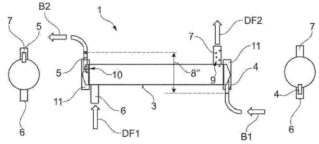
[0059]Apart from the (substantially) cylindrical portion on which the nozzles 6, 7 are arranged, the housing 3 also comprises a dialyzer cap 11 on each of the two end faces. The respective dialyzer cap 11 forms the blood inlet and blood outlet nozzles 4, 5 which in the present case are arranged to extend in the axial direction of the dialyzer. Of preference, the dialyzer cap 11 is configured so that the air bubbles 10 in the blood chamber can attach to or accumulate on the same without impairing the blood purification. In contrast to the air bubbles 9 present in the solution chamber, such air bubbles 10 present in the blood chamber in the first embodiment cannot be or are difficult to be evacuated and, consequently, attach in the respective end area of the housing 3, i.e. in the area of the dialyzer caps 11.

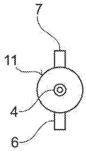
[0060]FIG. 1b depicts the dialyzer of FIG. 1a along its longitudinal axis wherefrom the 180° arrangement of the nozzles 6, 7 relative to each other is resulting. The blood inlet ...

second embodiment

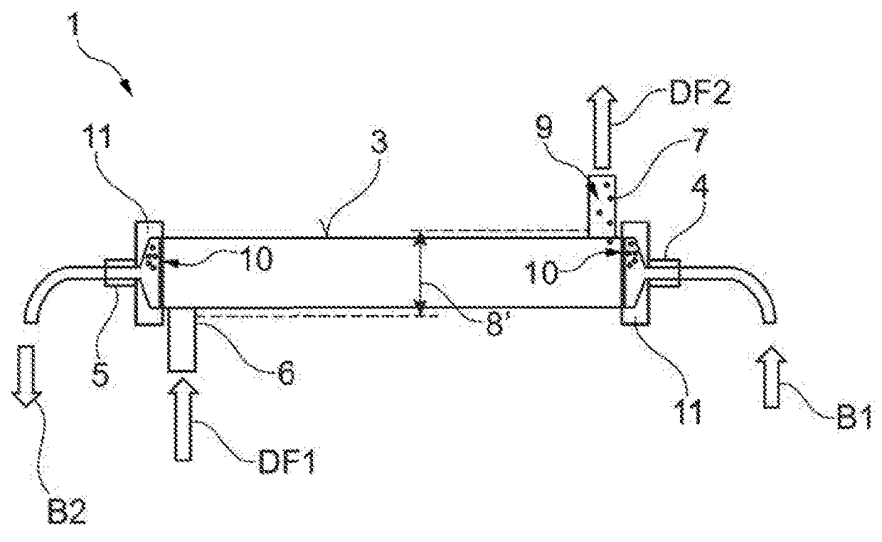
[0061]A second embodiment is shown in the FIGS. 2a to 2c. FIG. 2b illustrates the dialyzer of said embodiment in the side view, while in FIG. 2a it is shown in the perspective of a viewer on the one side (“left”) and in FIG. 2c it is shown in the perspective of a viewer on the other side (“right”) along its longitudinal axis. The essential components of this embodiment are known from the embodiment explained in connection with FIG. 1a and now will not be shown in detail once again to avoid repetitions.

[0062]The difference of said second embodiment from the first embodiment consists in the fact that the blood inlet nozzle 4 just as the blood outlet nozzle 5 are arranged to extend radially (and no longer axially) relative to the housing 3. Thus, apart from the height potential 8′ prevailing in the solution chamber, a height potential 8″ is also realized in the blood chamber. This saves axial construction space and reduces the risk of kinking of the respective tubes. Moreover, now leak...

third embodiment

[0064]A third embodiment is illustrated in the FIGS. 3a to 3c. FIG. 3b depicts the dialyzer of said embodiment in the side view, while in FIG. 3a it is shown in the perspective of a viewer on the one side (“left”) and in FIG. 3c it is shown in the perspective of a viewer on the other side (“right”) along its longitudinal axis. The essential components of this embodiment are known from the preceding embodiments and now will not be described in detail once again to avoid repetitions.

[0065]The third embodiment differs from the embodiments of the FIGS. 1 and 2 by the fact that all nozzles 4, 5, 6, 7 are arranged to extend tangentially relative to the housing 3. Consequently, the blood inlet nozzle 4 is not visible in the view from FIG. 3b. The blood drain from the blood outlet nozzle 5 in FIG. 3b steps out of the plane of projection in perspective, while the solution intake into the solution inlet nozzle 6 extends into the plane of projection.

[0066]Said tangential inflow and outflow pro...


PUM


Abstract

An extracorporeal blood treatment machine for carrying out a blood treatment including a machine front on which a hollow fiber filter module is arranged in a horizontal position, which hollow fiber filter module includes a cylindrical housing, a blood chamber having a blood inlet nozzle and a blood outlet nozzle and a solution chamber having a solution inlet nozzle extending transversely to the longitudinal direction of the hollow fiber filter module and a solution outlet nozzle extending transversely to the longitudinal direction of the hollow fiber filter module, the solution chamber being semi-permeably communicated at least in portions with the blood chamber, wherein a height potential is present in the horizontal position between the solution inlet nozzle and the solution outlet nozzle so that drainage of solution is enabled via one of the solution nozzles and evacuation of air bubbles is enabled via an other of the solution nozzles.

Description

CROSS REFERENCE TO RELATED APPLICATIONS[0001]This application claims priority to German application DE 10 2018 100 568.7 filed Jan. 11, 2018, the contents of such application being incorporated by reference herein.FIELD OF THE INVENTION[0002]The present invention relates to an extracorporeal blood treatment machine, such as for carrying out a dialysis treatment, according to the independent claim as well as to a hollow fiber filter module as defined in the dependent claims. Furthermore, the invention relates to use of the hollow fiber filter module. Generic blood treatment machines are employed so that blood treatment / purification can be carried out.BACKGROUND OF THE INVENTION[0003]The use of hollow fiber filter modules for blood treatment / purification in extracorporeal blood treatment machines is a wide-spread standard. Recently, increasing attention has been drawn to coupling the respective hollow fiber filter modules in a compact arrangement to the blood treatment machine such as...

Claims


Application Information

Patent Timeline
Patent Type & Authority Applications(United States)
IPC IPC(8): A61M1/36A61M1/16B01D63/02
CPCA61M1/3635A61M1/1623B01D63/02B01D2313/10B01D2313/12A61M1/16B01D61/243B01D61/28B01D2313/20
Inventor RITTER, KAI-UWE
Owner B BRAUN AVITUM
Why Eureka
Try Eureka