Work fixture, device and method for machining the cutting edge of cutting tools

a technology of cutting edge and work fixture, which is applied in the field of laser precision machining, can solve the problems of affecting the application of polycrystalline diamond forming machines, and affecting the quality of finished products

Inactive Publication Date: 2019-07-11
BEIJING UNIV OF TECH
View PDF74 Cites 1 Cited by
  • Summary
  • Abstract
  • Description
  • Claims
  • Application Information

AI Technical Summary

Benefits of technology

[0036]The roughness, machining precision and all other indicators of the cutting edge obtained from the present invention have significant improvement, such as that the roughness of the surface obtained from the machining of the present invention can reach 1.327 um. Compared with the s

Problems solved by technology

Even it has many excellent properties, the forming machine of Polycrystalline diamond is very difficult because of the high hardness, good wear resistance, and this seriously hindered its application.
During the grinding machining, due to the high hardness of diamond knife, there is a lot of difficulties in the machining.
Secondly, the grinding efficiency is very low and the grinding wheel consumption is very large.
As one of the most traditional machining methods, the efficiency of diamond grinding is very low.
The efficiency is also very low and cannot be u

Method used


Image

  • Work fixture, device and method for machining the cutting edge of cutting tools
  • Work fixture, device and method for machining the cutting edge of cutting tools
  • Work fixture, device and method for machining the cutting edge of cutting tools

Examples


embodiment 1

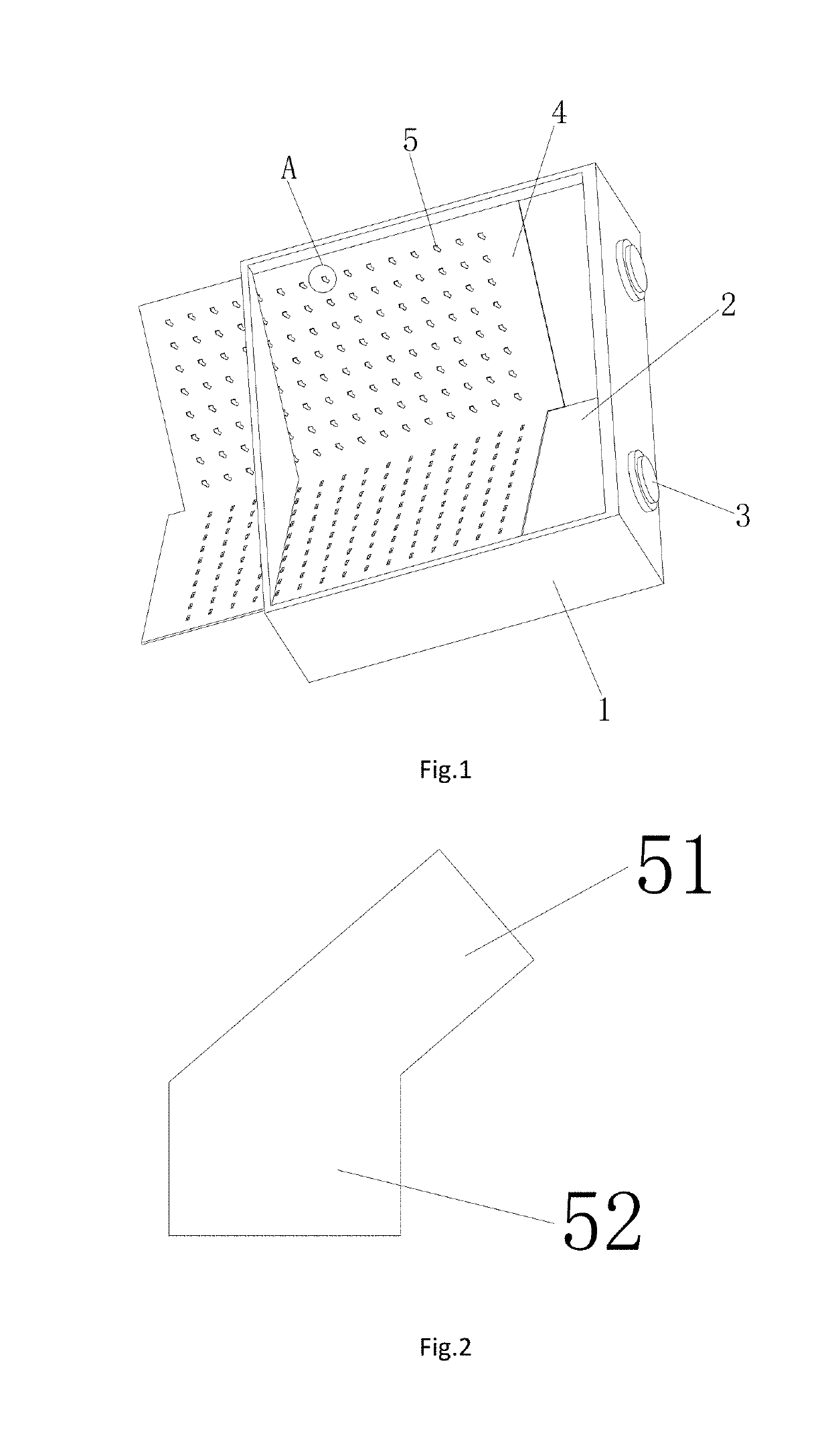
[0052]As shown in FIG. 1, the present invention provides a work fixture for machining the cutting edge of cutting tools. It compromises: fixture shell 1, beveled base 2, angle adjusting device 3 and feeding plate 4; Among them:

[0053]Fixture shell is a frame structure composed of a bottom plate and a four side plate and there is rotatable beveled base 2 arranged inside the fixture shell 1. The fixture shell 1 has an angle adjusting device 3 with readings arranged on its side wall and the angle adjusting device 3 is connected with the beveled base 2 in order to adjust the angle of the beveled base 2. There are two beveled bases in the present invention and they are arranged correspondingly. Each of the bevel bases 2 is connected with an angle adjusting device 3.

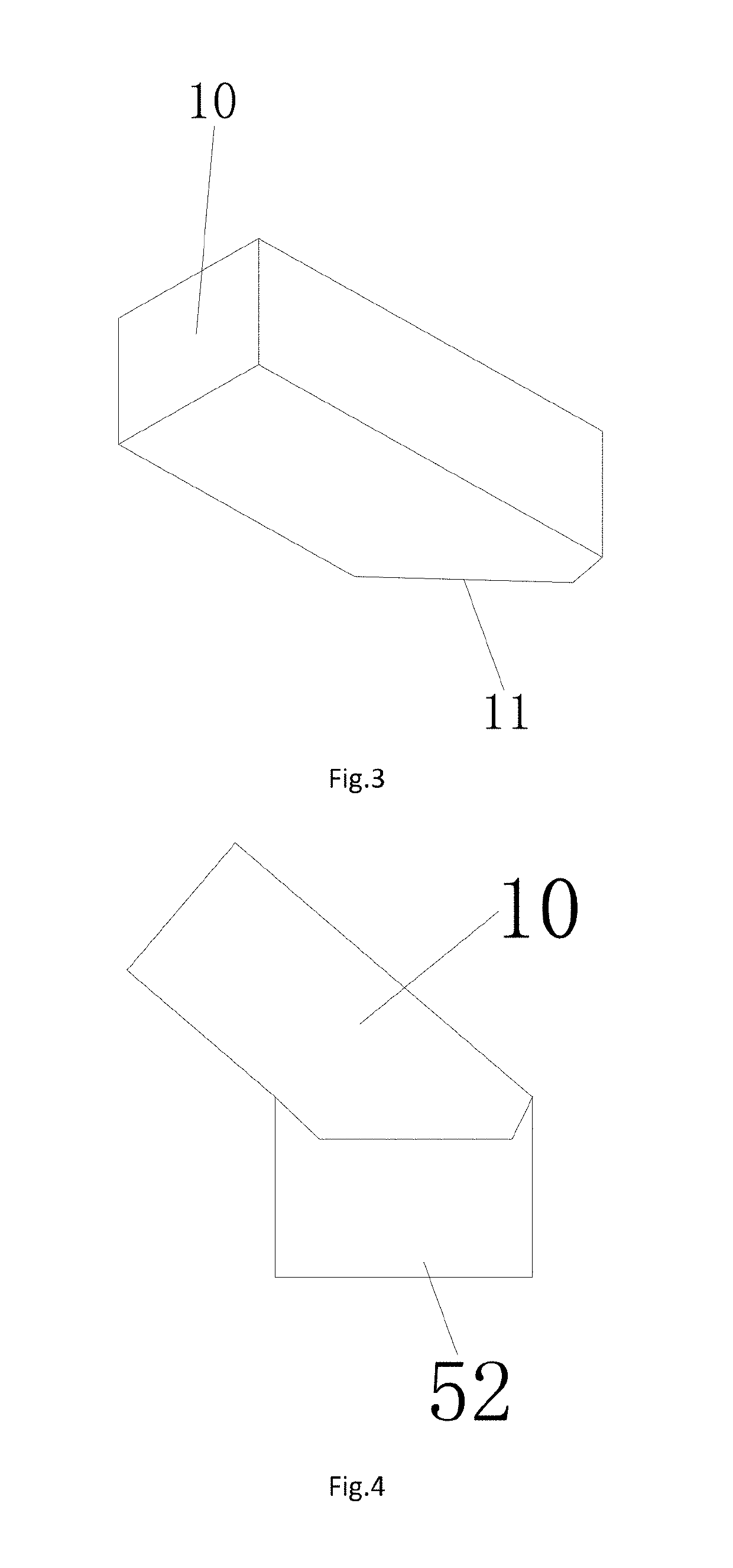
[0054]The beveled base 2 of the present invention clamped a feeding plate 4 and the feeding plate 4 can be prepared with a plurality of pieces, which can be fed on the idle plate during machining to meet mass production. The fe...

embodiment 2

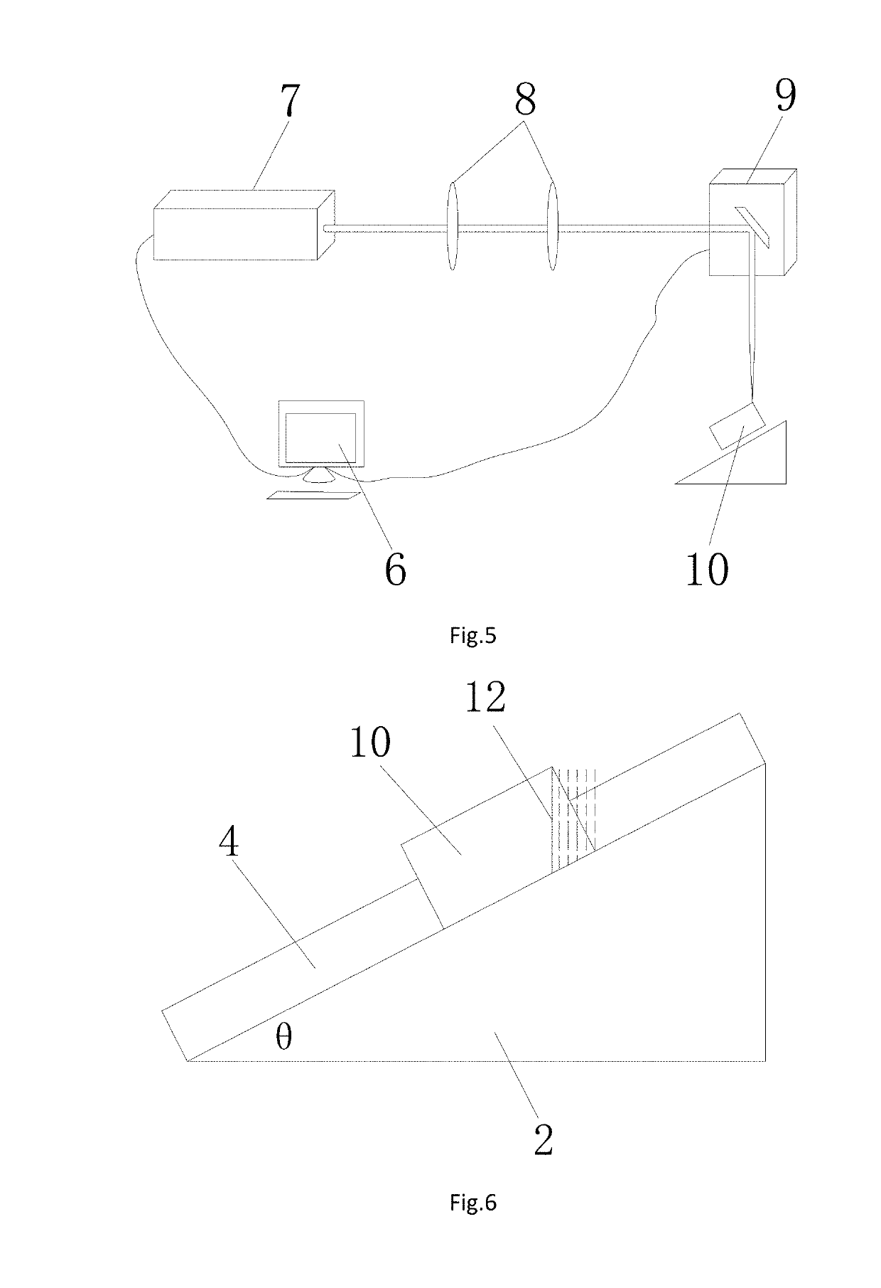
[0055]As shown in FIG. 5, the present invention provides a device for machining the cutting edge of cutting tools. It comprises: the work fixture, controller 6, laser 7, reflection lens 8 and laser galvanometer 9;

[0056]The controller 6 is connected with the laser 7 and the laser galvanometer 9 respectively. The controller 6 is used to set laser parameters of the laser 7 and use the laser galvanometer 9 to control the scanning path of laser. The laser beam passes through the reflection lens 8 and the laser galvanometer 9 to make the incident direction perpendicular to the datum plane and shot on the cutting tool to be machined 10 on the feeding plate 4, completing the machining of the cutting edge of the cutting tool 11. The ground surface is the datum plane.

[0057]Preferably, the present invention comprises a plurality of lasers, such as, but not limited to, a picosecond laser, a CO2 laser, a fiber laser, and a YAG laser, which can all use the machining method of cutting edge provide...

embodiment 3

[0058]The present invention provides a method for machining the cutting edge of cutting tools used in a device for machining the cutting edge of cutting tools. It comprises:

[0059]step 1. designing the shape of the grooves according to the shape and machining requirement of the cutting tools to be machined, clamping the cutting tools to be machined inside the grooves;

[0060]step 2. adjusting the angle needed for the machining of the cutting edge of cutting tools using the angle adjust device;

[0061]step 3. setting laser parameters and laser scanning path through controller. The present invention comprises a set of laser parameter choices, such as, but not limited to wavelengths of 100 nm˜1064 nm, 10.6 um, output power of 1 W˜500 W, pulse width of 10 ps˜300 ns and repetition frequency of 200 kHz˜10 MHz. The parameter mentioned above can apply to the machining method of cutting edge provided by the present invention;

[0062]step 4. completing the machining of the cutting edge of cutting to...


PUM

PropertyMeasurementUnit
Lengthaaaaaaaaaa
Timeaaaaaaaaaa
Timeaaaaaaaaaa

Abstract

The present invention discloses a work fixture, a device and a method for machining the cutting edge of cutting tools. The work fixture comprising: rotatable beveled base inside the fixture shell, the angle of the beveled base can be adjusted by the angle adjusting device; a feeding plate on the beveled base, on which a plurality of grooves are equispaced on the plate for clamping the cutting tools to be machined and completing the machining of the cutting edge. The device and the method of the present invention comprising: a controller being connected with a laser and a laser galvanometer, respectively; the beam of the laser sequentially passing through the reflection lens and the laser galvanometer to make the incident direction perpendicular to the datum plane and shot on the cutting tool to be machined on the feeding plate, and completing the machining of the cutting edge. Wherein, the laser parameters include a wavelength of 100 nm˜1064 nm, 10.6 um; an average pulse power of 1 W˜500 W; a pulse width of 10 ps˜300 ns; and a repetition frequency of 200 kHz˜10 MHz. The present invention can obtain the required cutting edge by laser cutting the cutting part once, with which the output and the efficiency are greatly improved and the cost is reduced. All the indicators, such as the obtained cutting edge, the roughness and the machining precision are also improved significantly.

Description

TECHNICAL FIELD[0001]The present invention relates to the field of laser precision machining, and more particularly to a work fixture, a device and a method for machining the cutting edge of cutting tools.BACKGROUND OF THE INVENTION[0002]As a kind of superhard cutting tool material, diamond has been used in cutting machining for hundreds of years. In the course of the development of cutting tools, from the late 19th century to the middle of the 20th century, the high-speed steel is the main representative of cutting tool materials. In 1927, Germany first developed cemented carbide cutting tool material and had it widely used; In the twentieth fifties, Sweden and The United States developed synthetic diamond respectively, indicating that cutting tools have entered an area where the superhard material is the representative. In the twentiethseventies, polycrystalline diamond (PCD) was synthesized by high-pressure synthetic technology, which solved the problem of scarce and expensive na...

Claims


Application Information

Patent Timeline
IPC IPC(8): B23K26/40B23K26/082
CPCB23K26/40B23K26/082B23K2101/20B23K26/38B23K26/402B23K37/0443B23K26/702B23K26/0624B23K2103/00B23K2103/52
Inventor JI, LINGFEIWANG, WENHAOYAN, TIANYANGJIANG, RUIWANG, SICONGLIN, ZHENYUANYANG, QIANG
Owner BEIJING UNIV OF TECH
Why Eureka
Try Eureka