Assembly and method for enabling rotational motion in a vehicle or mobile working machine

Active Publication Date: 2019-07-11
PONSSE
View PDF7 Cites 0 Cited by
  • Summary
  • Abstract
  • Description
  • Claims
  • Application Information

AI Technical Summary

Benefits of technology

The invention is a device that enables the frame of a vehicle or working machine to rotate, such as a cab or cargo space, with respect to the operating surface. This is important because it reduces the fluctuations and instability caused by the vehicle's movement. It also allows for manual control and adjustment of the frame's position for various situations, such as working on a slope or lifting a major load. This reduces stress on the frame and axles, requiring less maintenance and repair.

Problems solved by technology

As a result of such fluctuations, the stability of a working machine is compromised.
These fluctuations are the more severe, the rougher the terrain and the higher the speed of a moving vehicle.
Such a solution only works in a limited manner when there is a significant mass discrepancy between the frames.
Thus, the lighter frame is not in all cases capable of steadying the fluctuations of the heavier frame.

Method used


Image

  • Assembly and method for enabling rotational motion in a vehicle or mobile working machine
  • Assembly and method for enabling rotational motion in a vehicle or mobile working machine
  • Assembly and method for enabling rotational motion in a vehicle or mobile working machine

Examples


Embodiment Construction

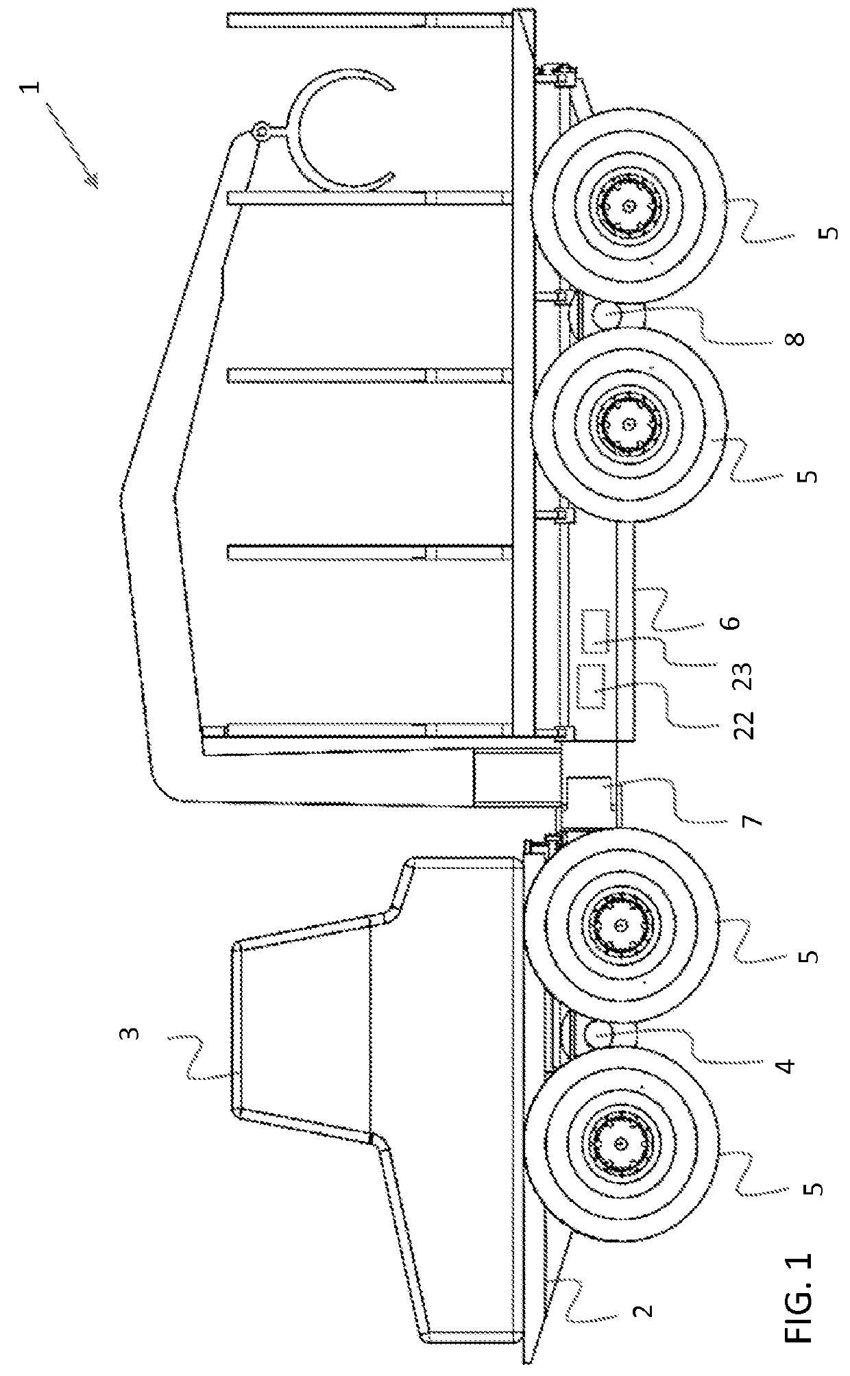
[0040]In the present figures, the assembly or method for enabling rotational motion in a vehicle or mobile working machine has not been presented in scale, but the figures are schematic, expressing the structure and operation of preferred embodiments in principle. Thus, the structural elements designated with reference numerals in the accompanying figures correspond to structural elements denoted with reference numerals in this specification.

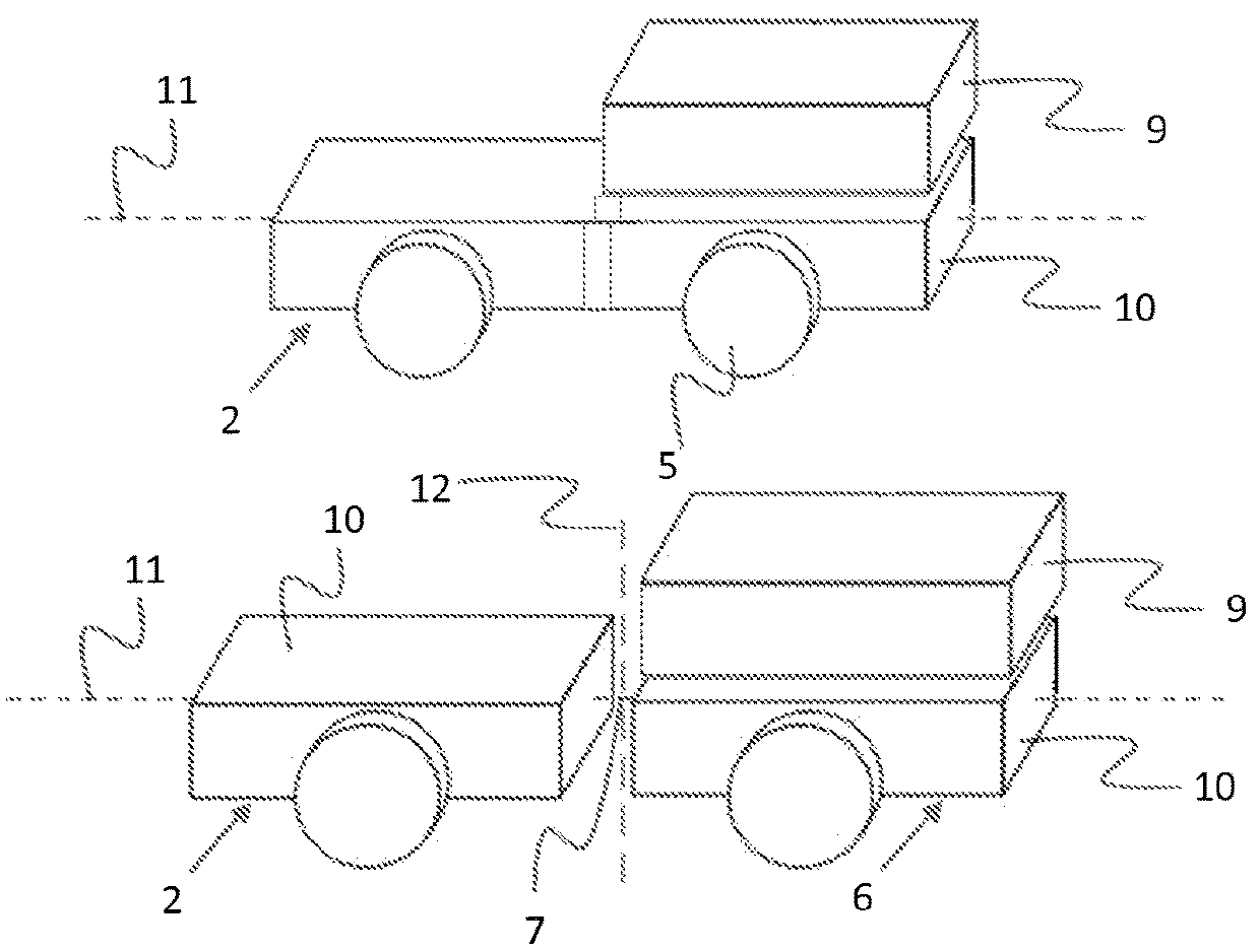
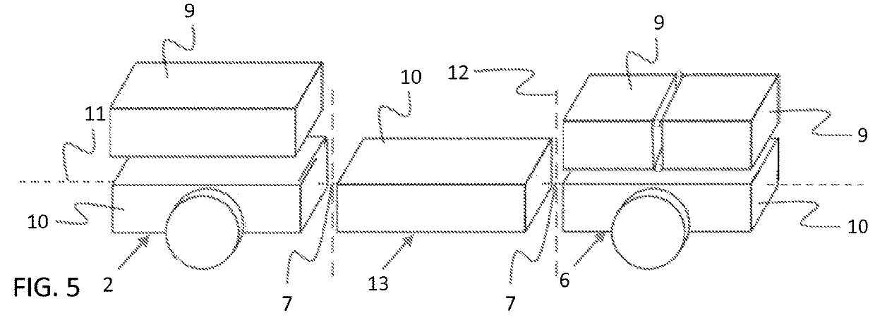
[0041]In terms of its structure and operation, the present assembly will next be portrayed mostly in reference to forest machinery. Although the presented embodiment therefore comprises a frame-steered forest machine 1, the present assembly does not limit itself to just this operating environment but the assembly is also capable of being utilized in other vehicles or mobile working machines, both single- and multi-frame types, whether provided with frame steering or not. A few alternative solutions are indeed depicted in the appended FIGS. 2, 3,...


PUM


Abstract

An assembly for enabling rotational motion in a vehicle or mobile working machine is disclosed which includes at least two sections arranged in an overlying position relative to the vehicle's or working machine's working surface. A top section can be led to motion relative to a bottom section and a longitudinal rotation axis, the top section and the bottom section being movably coupled to each other by at least one trajectory element which generates a curvilinear trajectory. The relative motion of the top section and the bottom section proceeds along a curvilinear trajectory in a section plane which is perpendicular relative to the lengthwise rotation axis. The trajectory can be at least partly in the shape of a circular arc, the midpoint of this curvilinear trajectory being disposed below the bottom section. An actuator mounted on the vehicle or working machine affects the top section and / or the bottom section.

Description

BACKGROUND OF THE INVENTION[0001]The present invention relates to an assembly as set forth in the preamble of claim 1 for enabling rotational motion in a vehicle or mobile working machine.[0002]The present invention relates also to a method as set forth in the preamble of claim 19 for enabling rotational motion in a vehicle or mobile working machine.[0003]Various mobile vehicles and working machines are often forced to perform multiple operations on uneven grounds as well as on sloping surfaces, it being important that the motion elements such as the wheels and / or tracks of a vehicle or working machine make adequate contact with the ground. A good contact with the ground or other working surface ensures for example an advancement or drive capability for the vehicle, as well as a good traction between the working surface and the vehicle or working machine. It also enables a low surface pressure on the working surface and a good stability. Features such as these are particularly prono...

Claims


Application Information

Patent Timeline
IPC IPC(8): B62D33/10B62D21/20B62D33/077
CPCB62D33/10B62D21/20B62D33/077A01G23/00B62D21/18A01G23/003B62D21/186B62D53/021B62D53/023B62D53/02
Inventor HUKKANEN, PENTTI
Owner PONSSE
Why Eureka
Try Eureka