
System and method for stick-slip vibration mitigation

a technology of vibration mitigation and stick, which is applied in the field of system and method for reducing stick vibration, can solve the problems of drill-string and/or drilling rig damage, drill-string damage, drill-string damage, etc., and achieve the effects of reducing stick vibration, reducing stick vibration, and reducing stick vibration

Active Publication Date: 2019-07-11
CONOCOPHILLIPS CO
View PDF0 Cites 2 Cited by
  • Summary
  • Abstract
  • Description
  • Claims
  • Application Information

AI Technical Summary

Benefits of technology

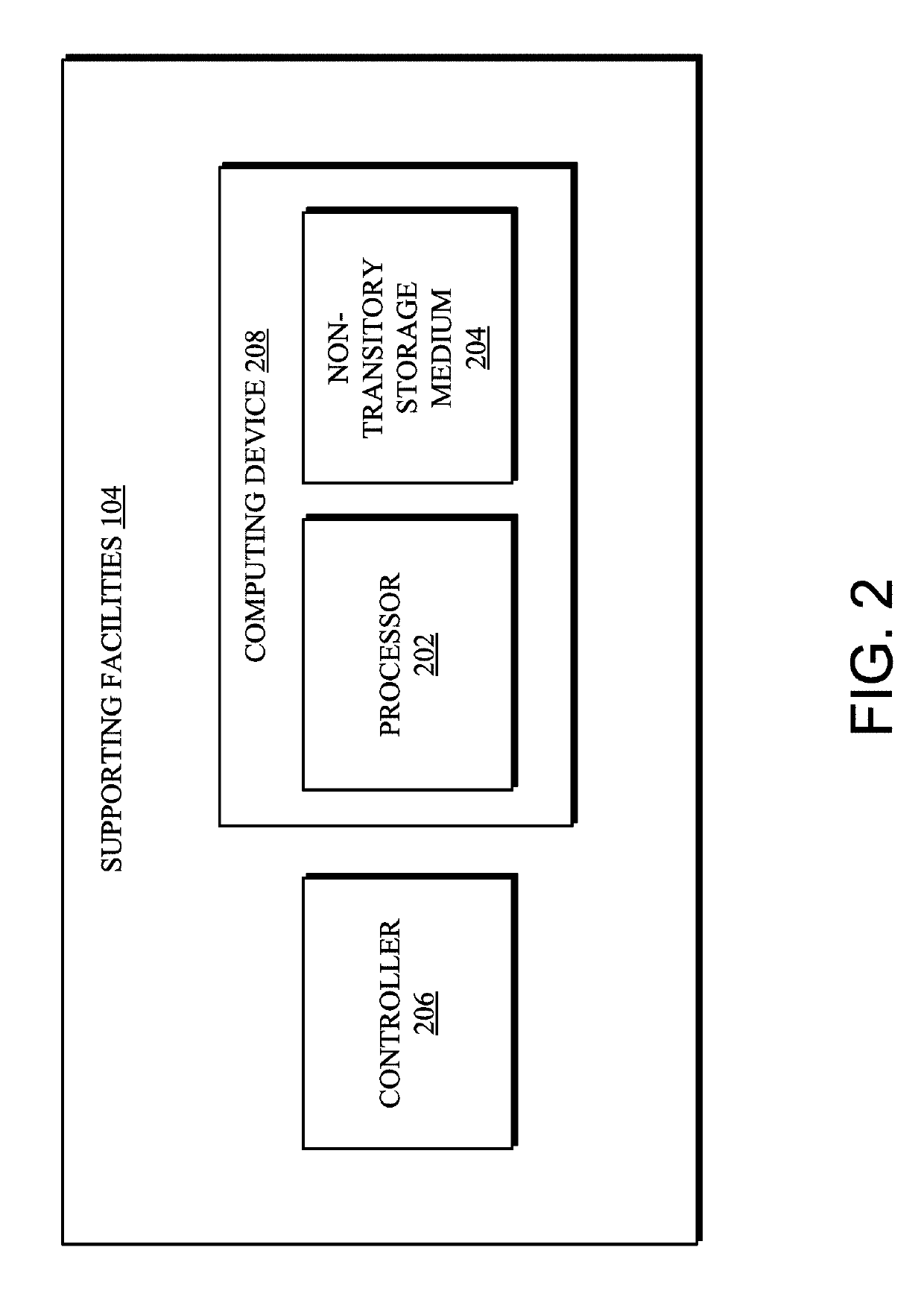
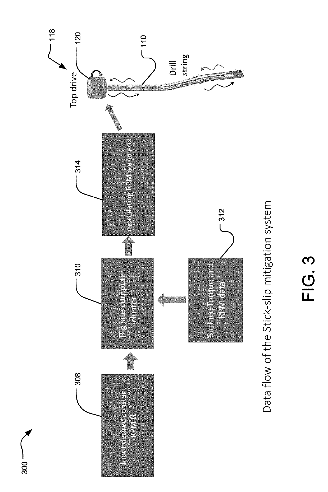
The present invention is about a system and method for reducing vibration in a drill-string in a wellbore. The system includes a sensor, processor, and non-transitory storage medium. The system measures the torque of the drill-string and identifies multiple vibration modes. The processor determines a controller setting that reduces the reflectivity of vibration energy at the vibration modes. The controller setting is then sent to a controller to reduce the vibration modes. The technical effect of the present invention is to improve the efficiency of the drilling process by targeting and reducing multiple vibration modes during the drilling process.

Problems solved by technology

A drill-string of a drilling rig can exhibit a variety of vibrations during use that may damage the drill-string and / or the drilling rig.
When a portion of the drill-string that is stuck overcomes the static friction of the formation, the drill-string will suddenly speed up and release the stored energy, which can damage the drill bit, the drill-string, and / or the drilling rig, thereby increasing drilling costs.
This conventional approach is ineffective when a higher frequency exhibits a stronger or comparable energy level than the lowest frequency, which is a common scenario.
In such a scenario, while the lower frequency of the vibration is reduced, the higher frequency remains strong, which results in continued stick-slip vibration.

Method used


Image

  • System and method for stick-slip vibration mitigation
  • System and method for stick-slip vibration mitigation
  • System and method for stick-slip vibration mitigation

Examples


Embodiment Construction

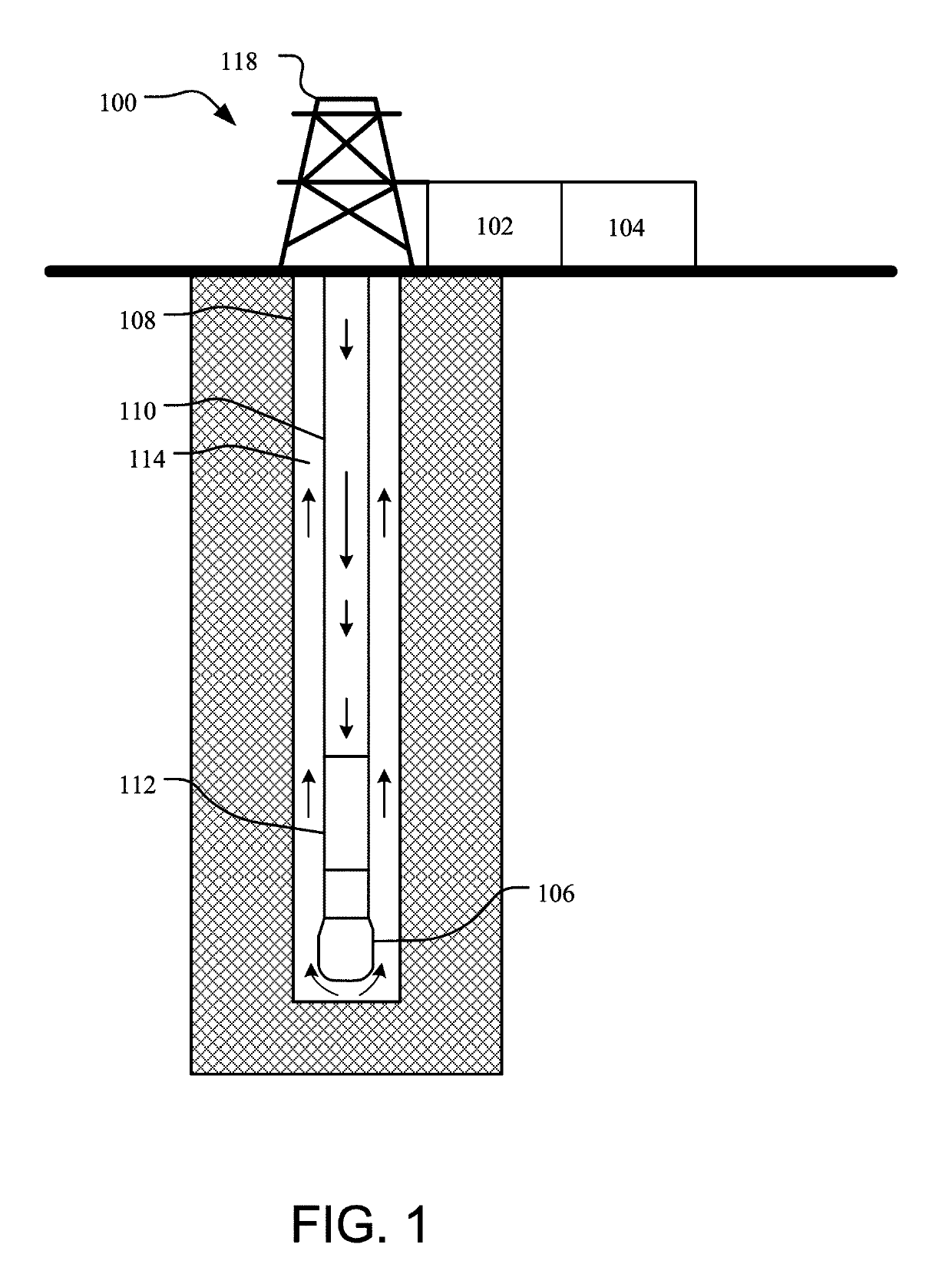
[0039]The following detailed description references the accompanying drawing that illustrates various embodiments of the present inventive concept. The illustration and description are intended to describe aspects and embodiments of the present inventive concept in sufficient detail to enable those skilled in the art to practice the present inventive concept. Other components can be utilized and changes can be made without departing from the scope of the present inventive concept. The following detailed description is, therefore, not to be taken in a limiting sense. The scope of the present inventive concept is defined only by the appended claims, along with the full scope of equivalents to which such claims are entitled.

I. Terminology

[0040]The phraseology and terminology employed herein are for the purpose of description and should not be regarded as limiting. For example, the use of a singular term, such as, “a” is not intended as limiting of the number of items. Also, the use of ...


PUM


Abstract

A stick-slip vibration mitigation system and a method of using the system are provided. The system includes a sensor, a processor, a non-transitory storage medium, and a controller. The system is operable to be used with a drill-string in a wellbore during a drilling process to mitigate stick-slip vibration of the drill-string.

Description

CROSS-REFERENCE TO RELATED APPLICATION[0001]This application claims the benefit of U.S. Provisional Application Ser. No. 62 / 613,986, filed Jan. 5, 2018, which is incorporated herein by reference in its entirety.BACKGROUND1. Field of the Invention[0002]The present inventive concept relates to a system and method to mitigate vibration of a drill-string during a drilling process. In particular, the present inventive concept concerns a system operable to obtain data regarding stick-slip vibration of the drill-string during the drilling process, and process the data to mitigate the stick-slip vibration, and a method of using the system.2. Description of Related Art[0003]A drill-string of a drilling rig can exhibit a variety of vibrations during use that may damage the drill-string and / or the drilling rig. One particular type of vibration, known as stick-slip vibration, occurs when a drill bit at a bottom of the drill-string is rotating at a different angular speed than a top drive motor ...

Claims


Application Information

Patent Timeline
Patent Type & Authority Applications(United States)
IPC IPC(8): E21B44/08E21B28/00
CPCE21B44/08E21B28/00E21B44/00
Inventor ZHA, YANGPHAM, SON V.
Owner CONOCOPHILLIPS CO
Learn More