
Method for testing multicore cable, method for manufacturing multicore cable assembly, and multicore cable test device

Active Publication Date: 2019-07-11
HITACHI METALS LTD
View PDF5 Cites 2 Cited by
  • Summary
  • Abstract
  • Description
  • Claims
  • Application Information

AI Technical Summary

Benefits of technology

This patent describes a method for testing a multicore cable that can accurately identify the connection between different parts of the cable without being affected by interference. This method can also be used for manufacturing multicore cable assemblies and testing devices.

Problems solved by technology

For such multicore cable having multiple insulated wires, it is difficult to use a color code so that every insulated wire has a different color insulation.
To test the multicore cable having multiple insulated wires, when a conductor of each insulated wire is exposed at an end portion and an electrode for supplying a test signal is directly brought into contact with the conductor, it is necessary to bring the electrode into contact with the conductor of every insulated wire to identify the correspondence relationship and it thus takes very long time for the test.

Method used


Image

  • Method for testing multicore cable, method for manufacturing multicore cable assembly, and multicore cable test device
  • Method for testing multicore cable, method for manufacturing multicore cable assembly, and multicore cable test device
  • Method for testing multicore cable, method for manufacturing multicore cable assembly, and multicore cable test device

Examples


embodiment

[0039]An embodiment of the invention will be described below in conjunction with the appended drawings.

[0040]Multicore Cable Test Device

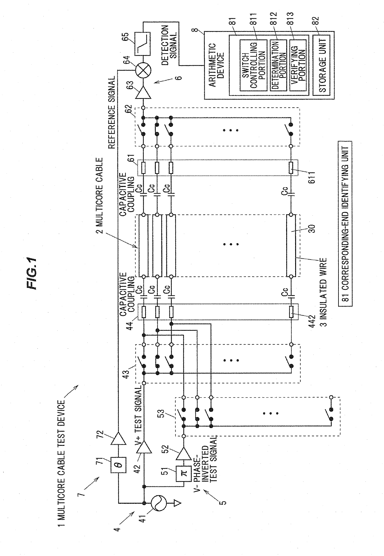
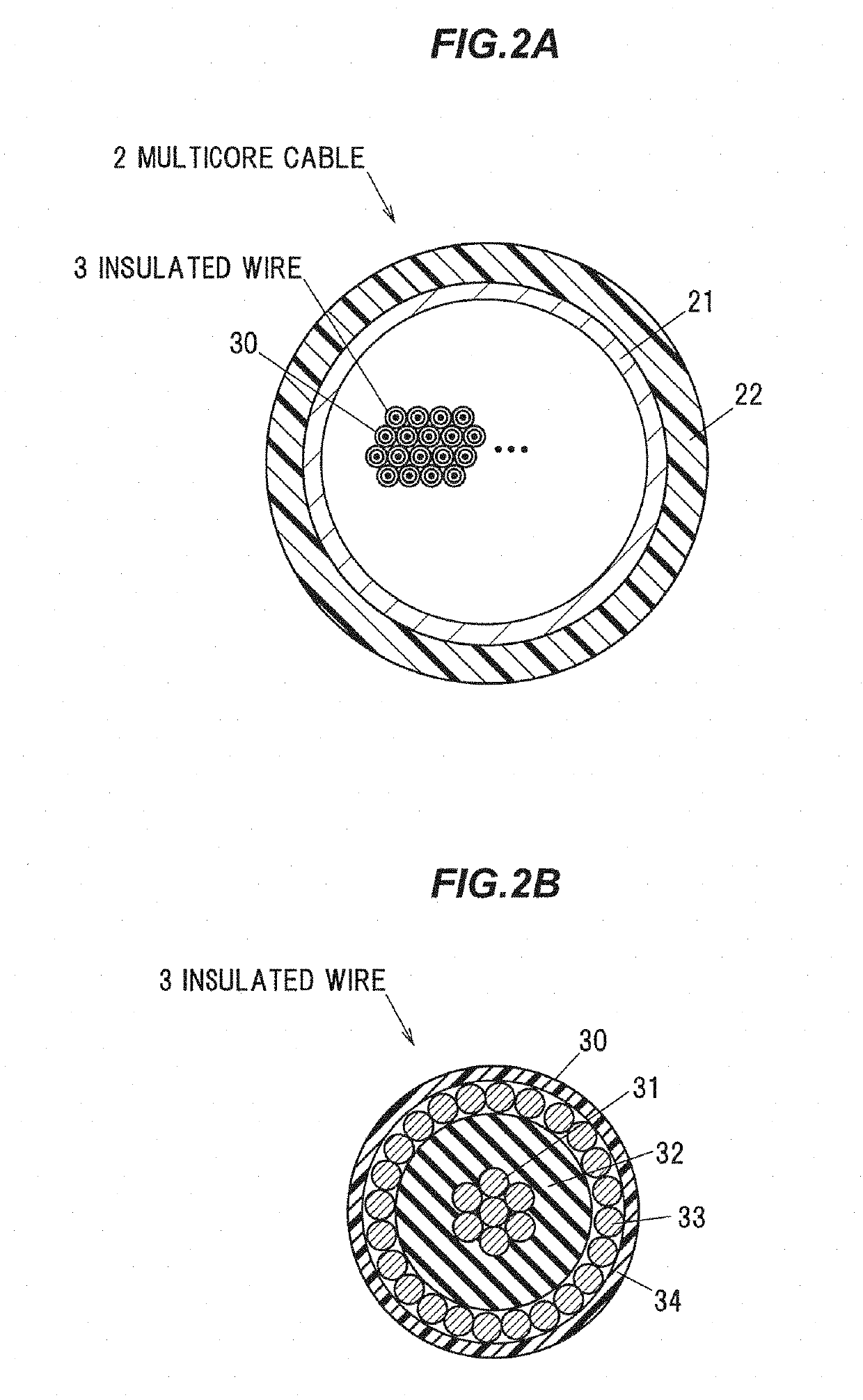
[0041]FIG. 1 is a schematic configuration diagram illustrating a multicore cable test device which is used in a method for testing a multicore cable in the present embodiment. FIG. 2A is a schematic cross-sectional view showing a multicore cable taken perpendicular to a longitudinal direction and FIG. 2B is a cross sectional view showing an insulated wire taken perpendicular to the longitudinal direction.

[0042]A multicore cable test device 1 is used to identify a correspondence relationship between one end portion and the other end portion of each insulated wire 3 exposed at both ends of a multicore cable 2. After identifying the correspondence relationship between one end portion and the other end portion of the insulated wires 3 of the multicore cable 2, the insulated wires 3 at both ends of the multicore cable 2 are respectively connected to conn...


PUM


Abstract

A method for testing a multicore cable including not less than three insulated wires to identify a correspondence relationship between one end portion and an other end portion of the insulated wires exposed from both ends of the multicore cable. The method includes inputting a test signal, by capacitive coupling, to an end portion of the tested insulated wire among end portions of the insulated wires exposed at one end of the multicore cable, inputting a phase-inverted test signal in an opposite phase to that of the test signal, by capacitive coupling, to an end portion of the insulated wire, other than the end portion of the tested insulated wire, and measuring voltages of output signals output respectively from end portions of the insulated wires exposed at the other end of the multicore cable to identify an other end portion of the tested insulated wire based on the measured voltages.

Description

[0001]The present application is based on Japanese patent application No. 2018-001333 filed on Jan. 9, 2018, the entire contents of which are incorporated herein by reference.BACKGROUND OF THE INVENTION1. Field of the Invention[0002]The invention relates to a method for testing a multicore cable, a method for manufacturing a multicore cable assembly, and a multicore cable test device.2. Description of the Related Art[0003]A multicore cable in which multiple insulated wires each having an insulation around a conductor are collectively covered with a jacket is known. For example, some of multicore cables used for medical probe cable are known to have, e.g., several tens to several hundreds of insulated wires (coaxial wires, etc.).[0004]For such multicore cable having multiple insulated wires, it is difficult to use a color code so that every insulated wire has a different color insulation. In addition, in case that the insulated wires are twisted together inside the multicore cable, e...

Claims


Application Information

Patent Timeline
IPC IPC(8): G01R31/02G01R1/04G01R31/08H01B13/016H01B13/06G01R19/165
CPCG01R31/023G01R1/0416G01R31/083H01B13/016H01B13/067G01R19/16576G01R31/08H01B13/22H01R43/28G01R31/60
Inventor SHIRAKAWA, YOHEIAGEISHI, YOSHITAKE
Owner HITACHI METALS LTD
Learn More