Row Detection System

a detection system and detection method technology, applied in the field of detection systems, can solve the problems of difficult access to farm land conditions and unreliable methods of increasing yields, and achieve the effect of low confidence level and high confidence scor

Inactive Publication Date: 2019-07-11
INTELINAIR INC
View PDF0 Cites 5 Cited by
  • Summary
  • Abstract
  • Description
  • Claims
  • Application Information

AI Technical Summary

Benefits of technology

[0021]Another embodiment includes the step of determining the slope, offset and distance for each row in a tile having a low confidence level and each adjacent tile having a high confidence score.
[0022]Another embodiment includes the step of selecting tiles adjacent to the low confidence tile with the adjacent tiles having a high confidence level
[0023]Another embodiment includes the step of calculating an average inter-row distance for each row identified in the low and high confidence tiles.
[0024]Another embodiment includes the step of calculating a maximum row angle and a minimum row angles for each row in the low and high confidence tiles, and the image analysis unit creates a parallel line for each row from the high confidence tile into the low confidence tile using the inter-row distance and row angles.

Problems solved by technology

However, as a single farm may encompass hundreds of acres, it is difficult to access the conditions of the farm land.
However, considering the large number of acres in the average farm, these observations are not a reliable method to increase yields.

Method used


Image

  • Row Detection System
  • Row Detection System
  • Row Detection System

Examples


Embodiment Construction

[0037]Referring now to the drawings which depict different embodiments consistent with the present invention, wherever possible, the same reference numbers will be used throughout the drawings and the following description to refer to the same or like parts.

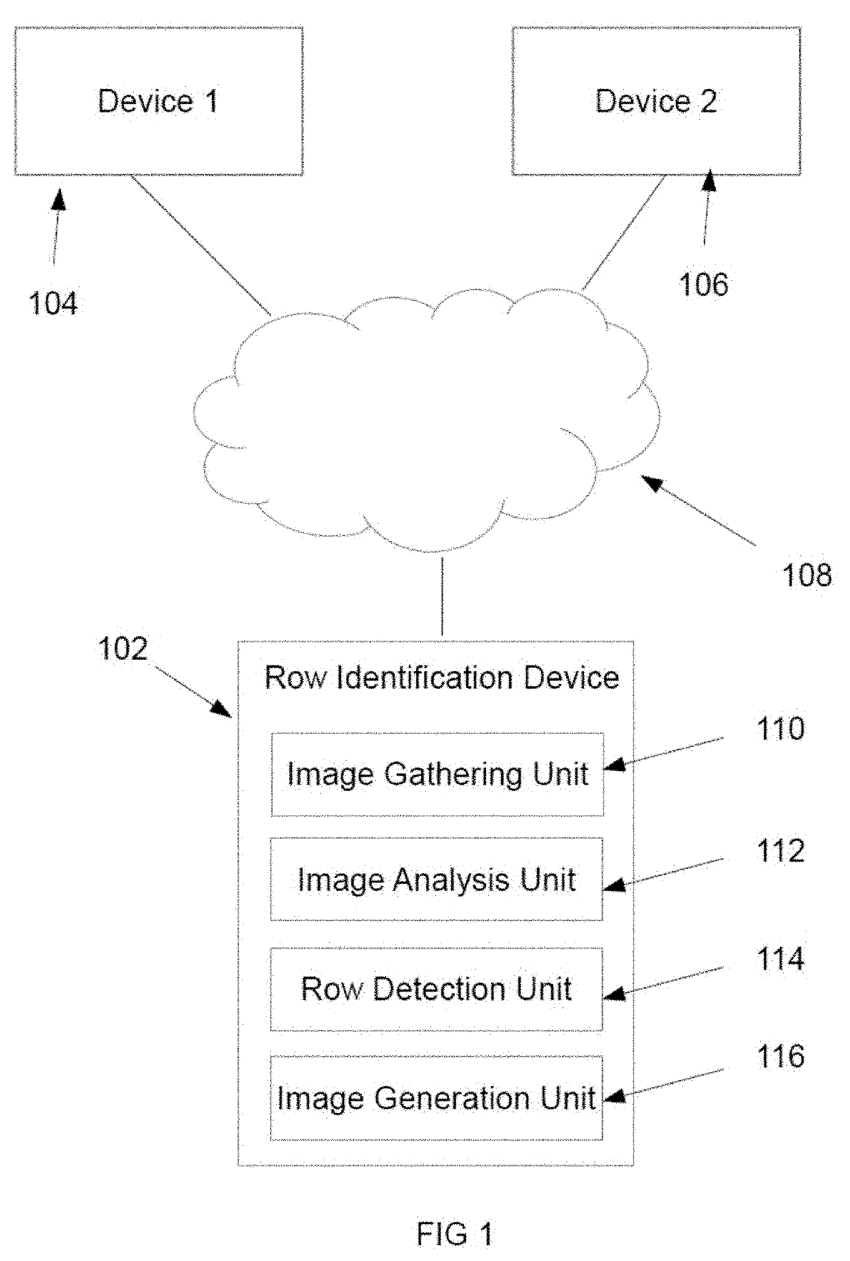
[0038]The row identification system 100 gathers medium to low resolution images gathered from an aircraft flying above 1,500 feet. Each image is then partitioned into equally sized tiles. Each tile is analyzed to identify objects within the tile. Adjacent tiles are then compared to identify similar objects in adjacent tiles. When the system 100 identifies an object that is inconsistent with adjacent objects, the system 100 identifies the area in the image containing the inconsistent object as an area requiring further statistical analysis. By comparing object areas to adjacent object areas to identify similar objects and dissimilar objects, the processing of large images covering multiple acres can be performed using less process...


PUM


Abstract

A row detection system including an image gathering unit that gathers a high-altitude image having multiple channels, an image analysis unit that segments the high-altitude image into a plurality of equally size tiles and determines an index value based on at least one channel of the image, where the image analysis unit identifies rows of objects in each image.

Description

CROSS REFERENCE TO RELATED APPLICATIONS[0001]This application is a non-provisional patent application that claims the benefit of and the priority from U.S. Provisional Patent Application No. 62 / 616,153, filed Jan. 11, 2018, titled ROW DETECTION SYSTEM.BACKGROUND OF THE INVENTION[0002]The agriculture industry comprises a large portion of the world's economy. In addition, as the population of the world increases annually, more food must be produced by existing agricultural assets. In order to increase yields on existing plots of farm land, producers require a clear understanding of plant and soil conditions. However, as a single farm may encompass hundreds of acres, it is difficult to access the conditions of the farm land.[0003]Currently, farmers rely on their observations of their land along with prior experience to determine the requirements to increase the yield of their farm land. These observations may include identifying locations of weeds, identifying plant illnesses and deter...

Claims


Application Information

Patent Timeline
Patent Type & Authority Applications(United States)
IPC IPC(8): G06K9/00G06T7/11G06V10/143
CPCG06K9/00657G06T7/11G06T2207/10032G06T2207/20021G06T2207/30188G06T7/12G06T7/168G06T2207/20056G06T7/136G06V20/188G06V10/143
Inventor NEFIAN, ARA VICTORKHACHATRYAN, HRANTKARAPETYAN, HOVNATANHOVAKYMIAN, NAIRA
Owner INTELINAIR INC
Why Eureka
Try Eureka