
Remote eye examination system

Active Publication Date: 2019-07-18
VPH INTPROP LLC
View PDF0 Cites 2 Cited by
  • Summary
  • Abstract
  • Description
  • Claims
  • Application Information

AI Technical Summary

Benefits of technology

The present invention provides a novel and non-obvious method, system and computer program for a remote eye examination system. The invention addresses deficiencies of the art in providing remote eye care by allowing doctors to delegate the physical refraction examination to an unskilled, non-professionals and have confidence they provided accurate and reliable information to diagnose and treat the patient's refractive error. The invention also addresses the rising cost of eye care by enabling eye care providers with multiple physical locations to better distribute staff and load-balance resources across entire systems, reaching more patients with less strain on optometrists and ophthalmologists. The invention also allows remote doctors to provide eye care services for multiple locations at the same time and over long distances by using an intuitive refractive software that makes the non-licensed staff's decisions based on a multitude of patient responses, and provides a warm, inviting, and professional interaction directly with a refractionist runs the invention in a professional setting.

Problems solved by technology

In smaller facilities, there may not be sufficient volume to keep an optometrist fully occupied.
Thus, optometrists in traditional facilities often waste time, waiting in between patient appointments.
As this capacity would otherwise not produce any revenue, eye care providers are able to invoice remote patient visits at a lower billing rate than what such providers would normally offer.

Method used


Image

  • Remote eye examination system

Examples


Embodiment Construction

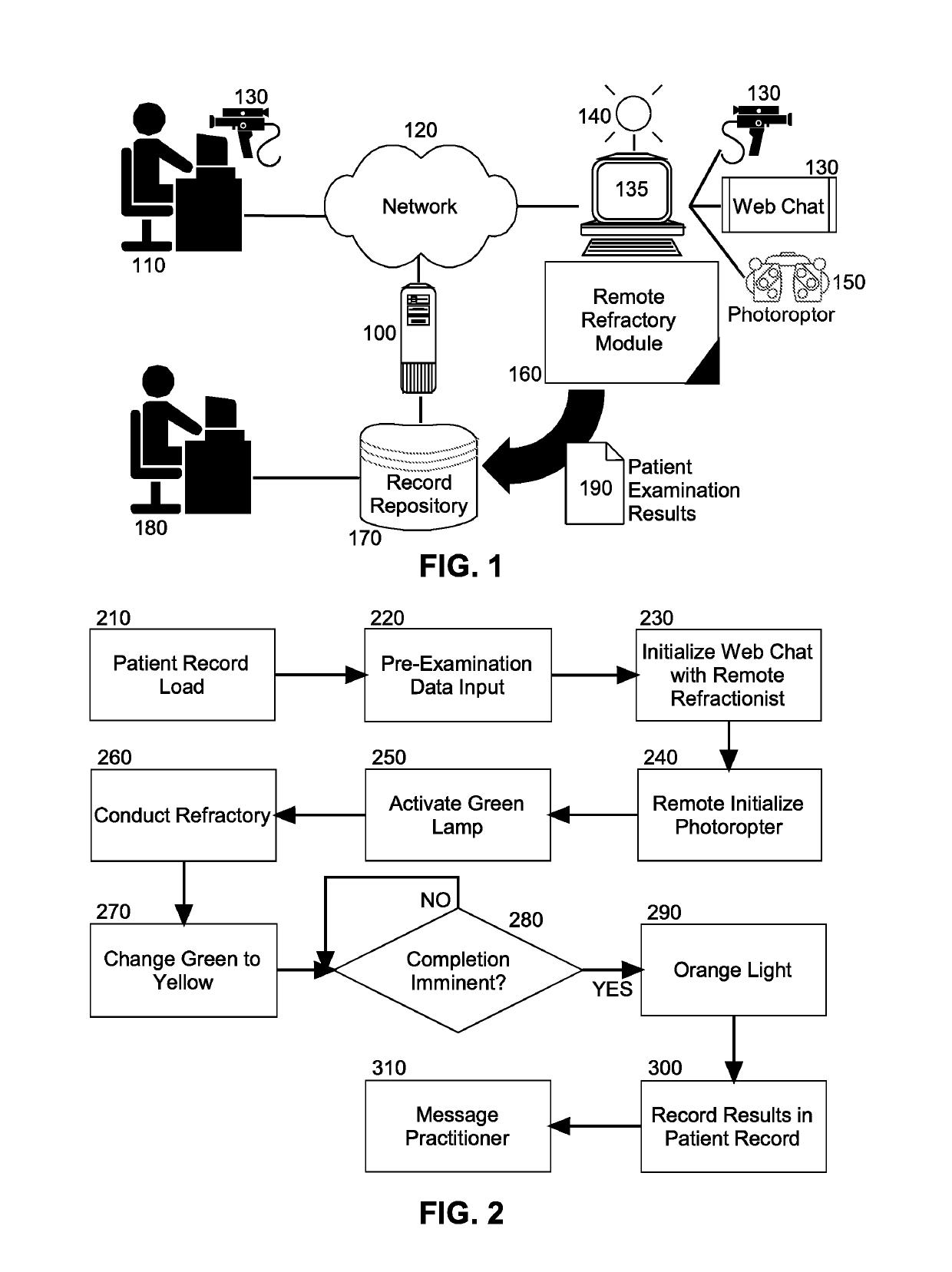
[0016]Traditional refraction had to been done by a licensed optometrist or ophthalmologist located onsite directly controlling the phoropter. The REES software allows the phoropter to be controlled at a remote location by a refractionist through a simple and user friendly interface controlled by a complex and intuitive algorithm which assists & prompts the operator to ask questions to a patient, then intuitively make complex decision on the patient's refractive error based on the patient's responses. Then, the refractive data is telemetered to a server, from which a remote doctor reviews such data and finalizes the prescription.

[0017]In further illustration, FIG. 1 is schematic illustration of a REES. As shown in FIG. 1, a remote refractionist 110 is communicatively linked to a local computing device 135 from over a computer communications network 120. The local computing device 135 which includes memory and at least one processor, hosts the execution of remote refractory module 160...


PUM


Abstract

A remote eye examination method includes initiating a remote chat session between a local computing device coupled to a phoropter, and a remote computer, and initializing the phoropter for remote control by the remote computer. Then, a multi-colored lamp is activated in a first color until a determination that a refractory examination utilizing the phoropter has commenced. Thereafter, responsive to a determination that the examination has commenced, the multi-colored lamp changes to a second color, and movement of portions of the phoropter are commanded as directed by the remote computer, data is recorded into a patient record and a progression of the examination monitored. Finally, on condition that a threshold period of time before a conclusion of the refractory examination is detected, the multi-colored lamp changes to a third color and upon conclusion of the examination, a message transmitted to a remote account indicating access to the patient record.

Description

BACKGROUND OF THE INVENTIONField of the Invention[0001]The present invention relates to the field of telemedicine and more particularly to a remote eye examination system and methodology.Description of the Related Art[0002]A patient's access to eye care has long been an issue in small towns and remote areas across the U.S. (and across the world). Patients who are able to drive, are sometimes force to travel hundreds of miles for eye care. Unfortunately, those who lack the ability to drive such long distances often go without care. Tragically, this not only affects adults but numerous children as well. Poor vision in children can lead to visual developmental delays which, if untreated, can result in permanent vision loss. Furthermore, it is estimated that up to 80% of a child's learning is done visually—putting those who do not have access to eye care at a major disadvantage.[0003]Historically, eye care could only be performed if an eye care provider had a doctor physically on locati...

Claims


Application Information

Patent Timeline
IPC IPC(8): A61B3/028G16H10/60H04L29/06G08B5/36H04L12/24A61B3/00
CPCA61B3/0285G16H10/60H04L65/1069G08B5/36H04L41/0681A61B3/0033G16H40/67G16H80/00A61B3/028
Inventor BROCWELL, CHRISTOPHER BRADLEYMORENO HERNANDEZ, ALVARO JOSESTANTON, DANIEL SCOTT
Owner VPH INTPROP LLC
Learn More