

Magnet for NMR analyzer and NMR analyzer using the same
- Summary
- Abstract
- Description
- Claims
- Application Information
AI Technical Summary
Benefits of technology
Problems solved by technology
Method used
Image

Examples
embodiment 1
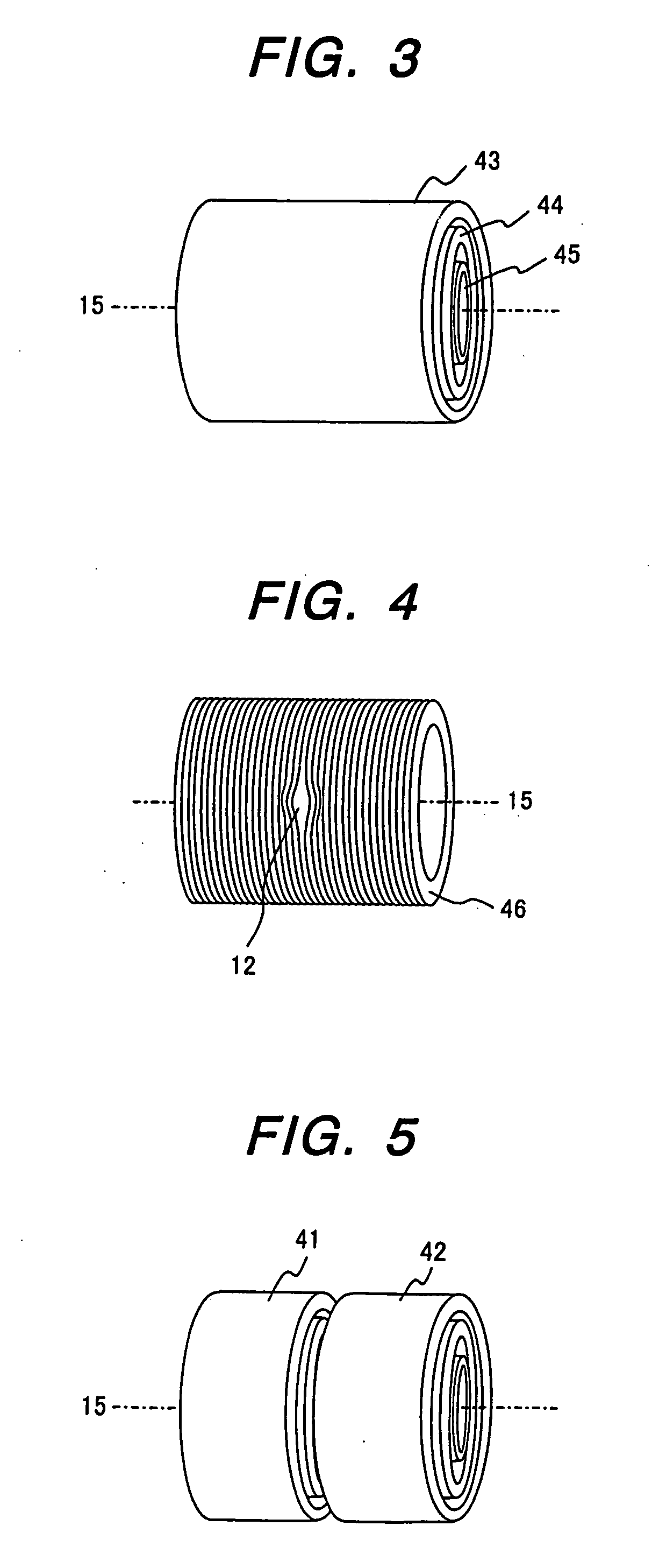
[0064] As shown in FIG. 3, a multilayer coil group in which a plurality of coils 43, 44 and 45 are coaxially nested and wound is disposed so that the axis 15 is horizontal. As shown in FIG. 4, each coil is wound so that a clearance 12 is created in the central portion of each coil 46 to create a port for accessing the magnet's central portion.
[0065] The size of the clearance 12 in the central portion of the coil winding provided for ensuring a port is approximately 40 mm wide. The coil wire is wound such that the clearance is made as small as possible.
[0066] Furthermore, without disturbing the clearance, a shim coil group (not shown) is disposed outside the multilayer coil group to compensate for an axisymmetric and nonaxisymmetric error magnetic field. In addition, another shim coil group is disposed inside the multilayer coil.
[0067] In this embodiment, the multilayer coil group consists of nine coils (not shown). Three coils located radially on the outer side are wound with NbT...
embodiment 2
[0093] In embodiment 1, a coil is wound such that a clearance 12 is made in the central portion of the coil winding in order to create a sample insertion port. As an alternative, there is another method. In the method, instead of creating a clearance 12 in the central portion of the coil, as shown in FIG. 5, a solenoid coil group 1 (numeral 41 in FIG. 5) and a similar solenoid coil group 2 (numeral 42 in FIG. 5) both of which are wound around the same axis 15 are disposed with a given interval provided therebetween.
[0094] Coils used for this method are easy to make, and designing of the uniform magnetic field is also easy because the coil winding can be symmetrical. Also, a relatively uniform electromagnetic force can be applied, which is an advantage in terms of electromagnetic force resistance.
[0095] However, that configuration has the same effect as that resulted from the clearance between coils being made large, and the strength in the central magnetic field significantly decr...
embodiment 3
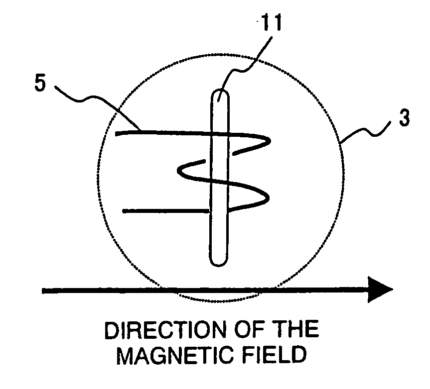
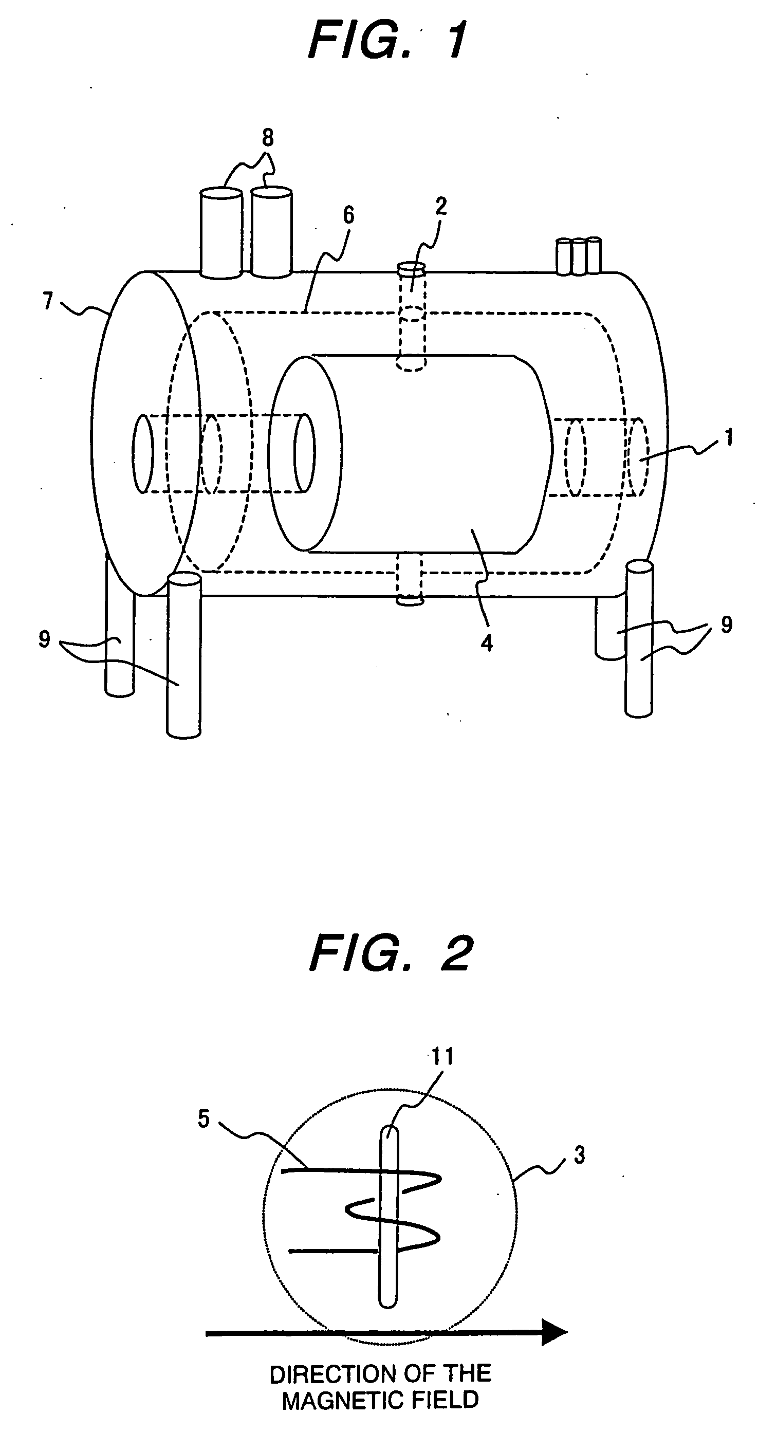
[0097] In embodiment 1, the magnetic axis 15 is horizontally oriented. In the present invention, the direction in which a magnetic field is generated is not limited to the horizontal direction. In this embodiment, a magnetic field is vertically generated.
[0098] In a conventional NMR analyzer, replacement of a sample is inconvenient because a magnetic axis is vertically oriented and a sample is inserted from above (2 m or more above the floor surface). In the present invention, the sample insertion port is located in the central portion of the magnet. Therefore, the position at which a sample is inserted is 2 m or less, thereby making sample replacement easy.
[0099] When reducing a spread of the leak magnetic field generated by a magnet by using a magnetic shield (magnetic shield room) made of ferromagnetic material, it is desirable to place the ferromagnetic shields at symmetrical locations from the center of the magnet so as to ensure the uniformity of the magnetic field. In the m...
PUM
 Abstract
Description
Claims
Application Information