
Fault detection device and method for switch driving circuit, and electronic device

Active Publication Date: 2019-07-18
MURATA MFG CO LTD
View PDF3 Cites 0 Cited by
  • Summary
  • Abstract
  • Description
  • Claims
  • Application Information

AI Technical Summary

Benefits of technology

This patent describes a method or device for detecting faults in the switch driving circuit of a DC-to-DC converter. The method involves directly or indirectly detecting the voltage or current waveform of the primary inductor, and then determining whether the primary switch is in a diode rectifying state or in a diode flyback state based on the waveform. By doing this, it becomes possible to detect any faults in the switch driving circuit. The technical effect of this invention is to allow for more accurate and reliable detection of faults in the switch driving circuit of a DC-to-DC converter.

Problems solved by technology

However, it cannot be accurately determined whether there is a fault by detecting a direction of an output voltage or current, as even in a normal state, the above-mentioned current reversion occurs occasionally, and a duration and frequency of the reversion are determined according to environments of practical applications.
Therefore, the above-described fault cannot be accurately determined by simple monitoring for the direction of the output voltage or current.
Therefore, in such cases, whether there is a fault in a converter cannot be determined.

Method used


Image

  • Fault detection device and method for switch driving circuit, and electronic device
  • Fault detection device and method for switch driving circuit, and electronic device
  • Fault detection device and method for switch driving circuit, and electronic device

Examples


Embodiment Construction

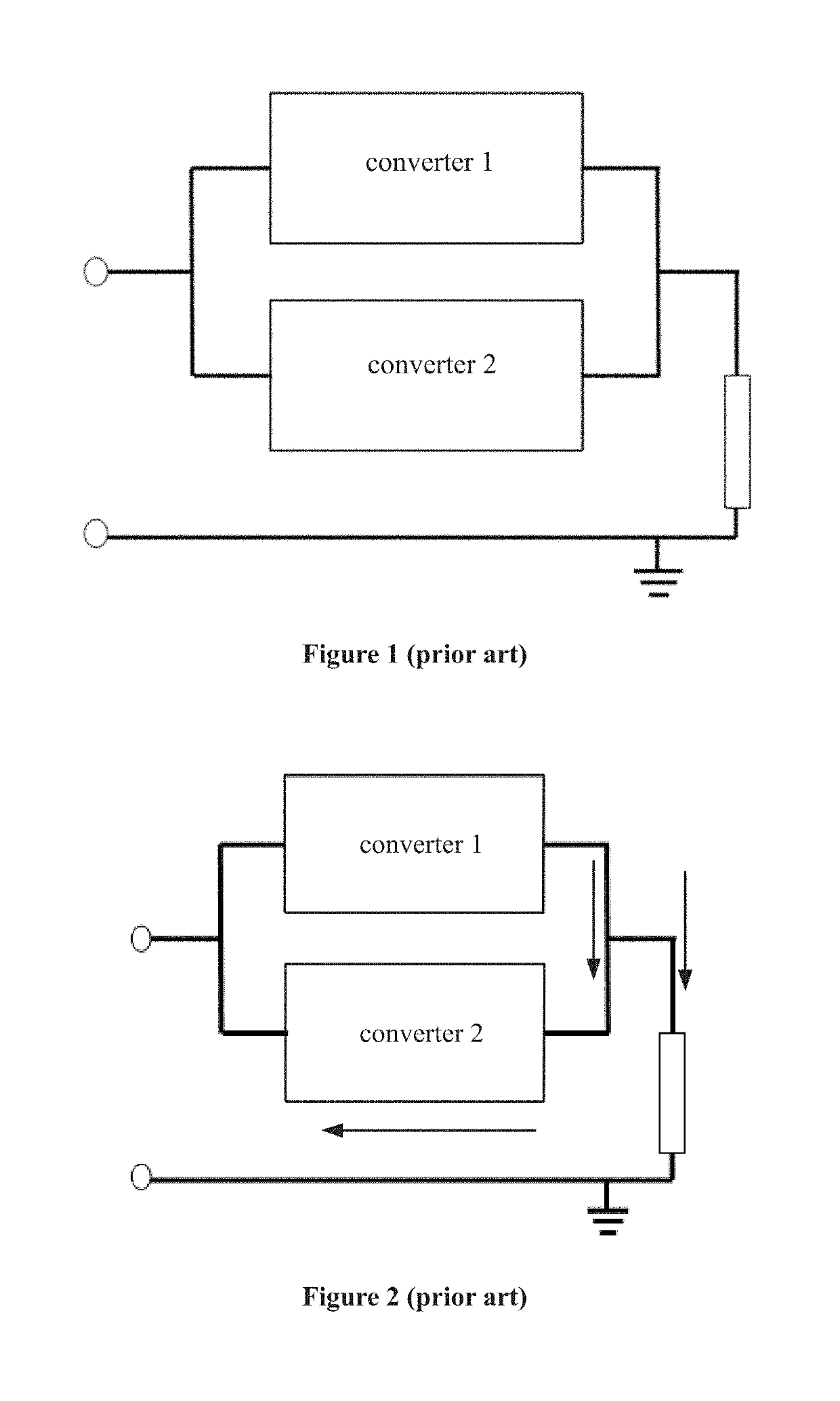
[0045]As described in the background, when a converter includes a switch rectifier circuit or a switch flyback circuit, if a switch driving circuit of a pre-stage circuit of the converter fails, existing solutions cannot effectively detect the fault in the switch driving circuit.

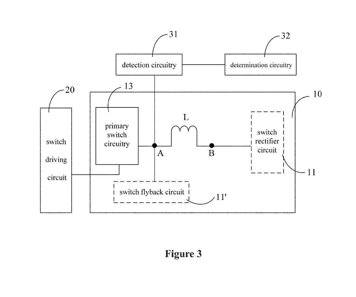
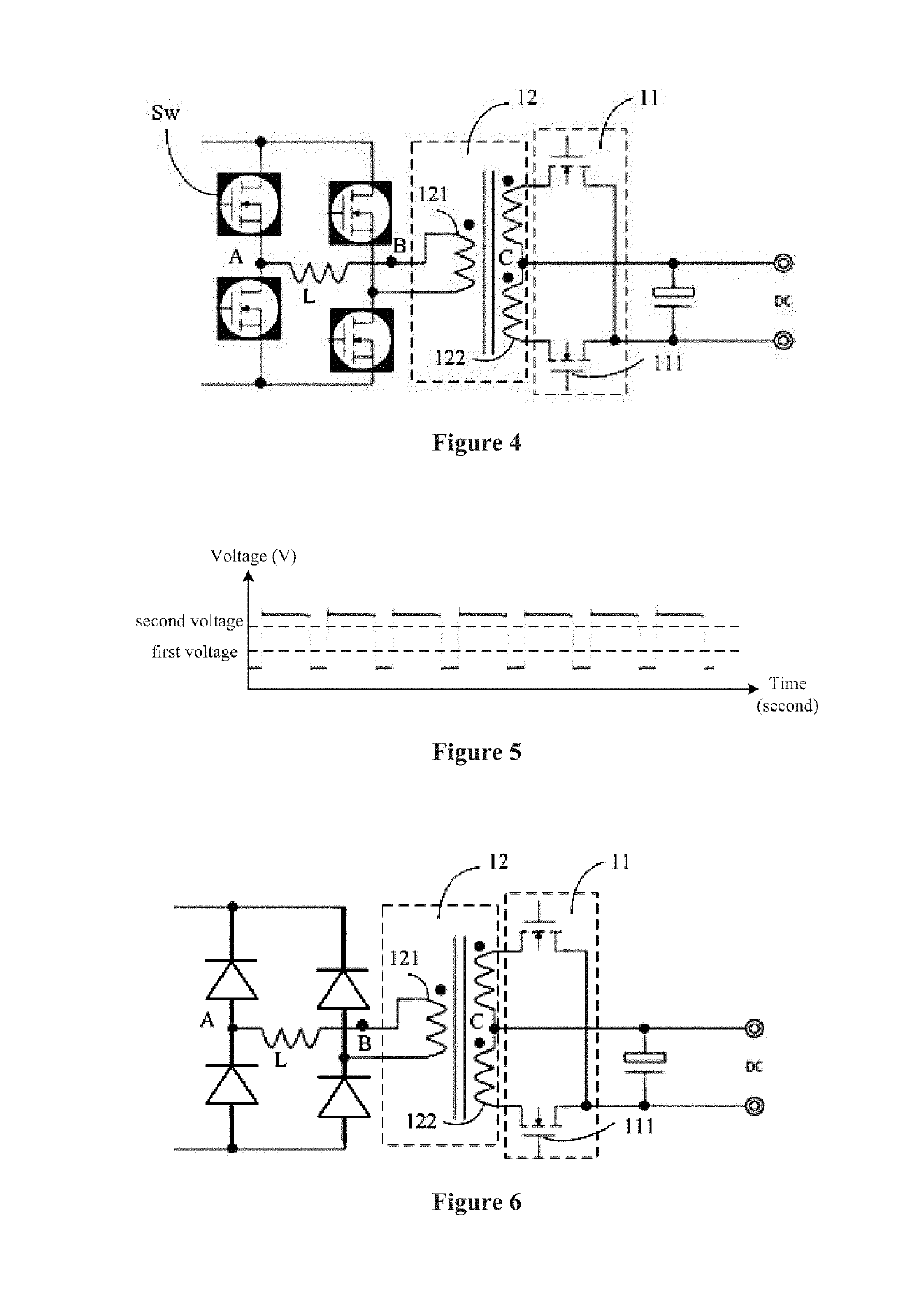
[0046]Preferred embodiments of the present disclosure provide fault detection method or device for the switch driving circuit of the DC-to-DC converter. A voltage waveform or a current waveform of at least one terminal of a primary inductor is directly or indirectly detected, and whether at least one primary switch is in a diode rectifying state or in a diode flyback state is determined based on the voltage waveform or the current waveform. In this way, whether there is a fault in the switch driving circuit of the DC-to-DC converter is able to be detected.

[0047]Solutions and advantages of preferred embodiments of the present disclosure will be described clearly in detail in conjunction with accompanying draw...


PUM


Abstract

A DC-to-DC converter includes at least one primary switch, a primary inductor, and a switch rectifier circuit or a switch flyback circuit. A switch driving circuit is structured to drive the at least one primary switch. A fault detection method includes directly or indirectly detecting a voltage waveform or a current waveform of at least one terminal of the primary inductor, and determining whether the at least one primary switch is in a diode rectifying state or in a diode flyback state based on the voltage waveform or the current waveform to detect whether there is a fault in the switch driving circuit.

Description

CROSS REFERENCE TO RELATED APPLICATIONS[0001]This application claims the benefit of priority to Chinese Patent Application No. 201810035324.7 filed on Jan. 15, 2018. The entire contents of this application are hereby incorporated herein by reference.BACKGROUND OF THE INVENTION1. Field of the Invention[0002]The present disclosure generally relates to circuit technology, and more particularly, to fault detection devices and methods for a switch driving circuit of a Direct Current (DC)-to-DC converter, and electronic devices.2. Description of the Related Art[0003]At present, multiple converters are usually coupled in parallel to provide a stable output or increase a total output power. As shown in FIG. 1, a maximum output power of two converters is 500 W, thus, a maximum load power that can be achieved is 1000 W. If a load's power is 1000 W and one of the converters fails, temperature can be monitored to detect which converter failed, and an alarm is generated accordingly. If the load'...

Claims


Application Information

Patent Timeline
IPC IPC(8): G01R19/165H02M1/08G01R19/17
CPCG01R19/16538H02M1/08G01R19/17H02M3/33576H02M3/158G01R31/2843G01R31/40H02M1/32
Inventor LI, QIANGWANG, XIAOJUN
Owner MURATA MFG CO LTD
Features
  • Generate Ideas
  • Intellectual Property
  • Life Sciences
  • Materials
  • Tech Scout
  • Unparalleled Data Quality
  • Higher Quality Content
  • 60% Fewer Hallucinations
Learn More