
Abnormality detection parameter adjustment display device

Active Publication Date: 2019-07-18
FANUC LTD
View PDF7 Cites 0 Cited by
  • Summary
  • Abstract
  • Description
  • Claims
  • Application Information

AI Technical Summary

Benefits of technology

The invention aims to offer a display device that can easily fix parameters used for abnormality detection.

Problems solved by technology

However, the failures caused in the mechanical facilities include a large number of abnormal patterns that cannot be detected with a simple threshold.
Thus, the operation of the mechanical facility can be determined to be abnormal if a pressure value higher than the upper limit threshold or lower than the lower limit threshold is detected.
However, this malfunction detection method using the thresholds cannot detect a deviation from a normal change in pressure as a malfunction or operation abnormality when the pressure detected by the pressure sensor falls within the range between the upper and lower limit thresholds.
However, it is not very easy to reflect user's feeling on whether or not to detect abnormality in case of deviation from expected values of the time-series data, on the setting of these parameters.
This is troublesome to the user.

Method used


Image

  • Abnormality detection parameter adjustment display device
  • Abnormality detection parameter adjustment display device
  • Abnormality detection parameter adjustment display device

Examples


Embodiment Construction

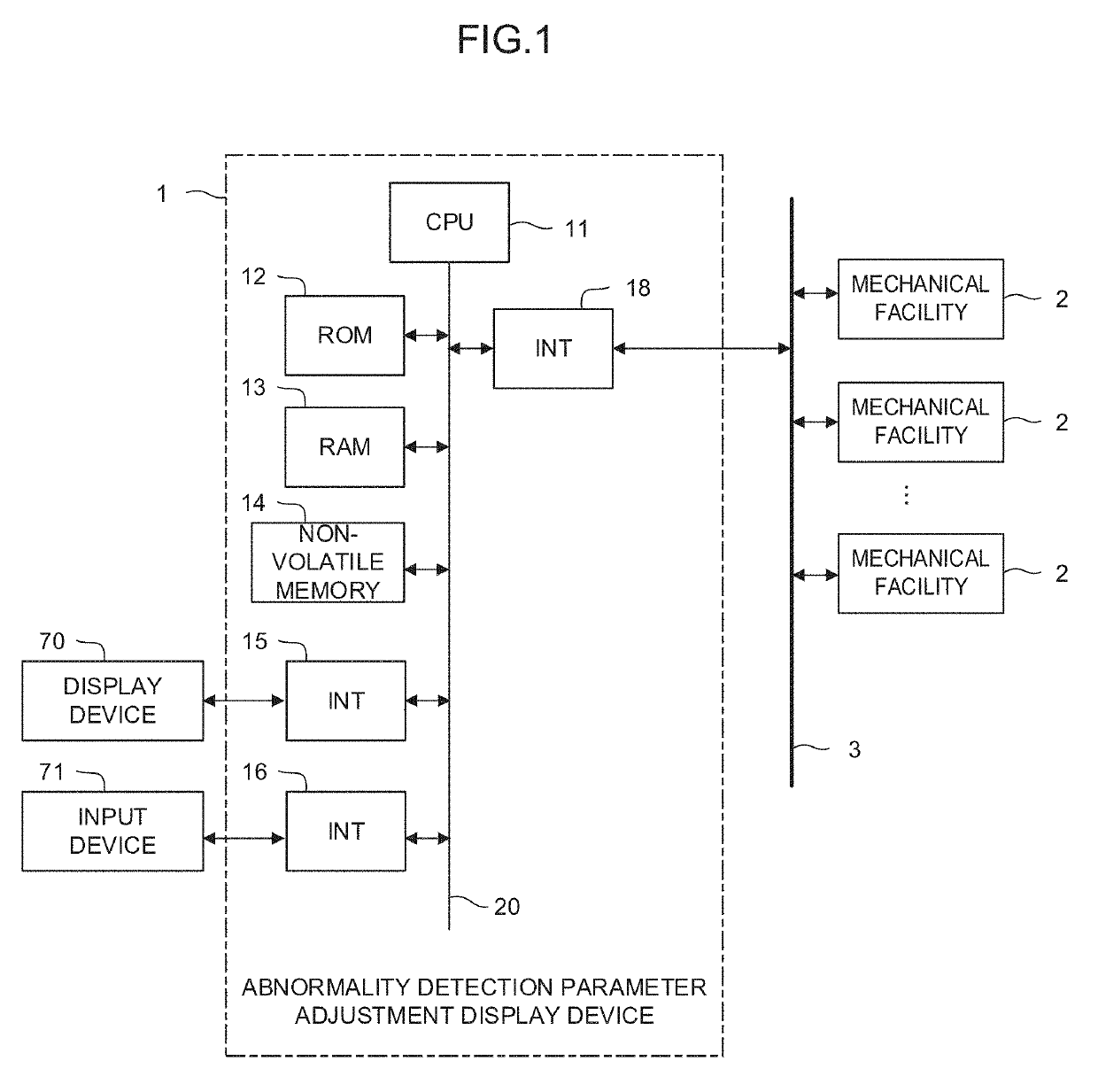
[0020]FIG. 1 is a schematic hardware configuration diagram showing the principal part of an abnormality detection parameter adjustment display device according to one embodiment of the present invention.

[0021]An abnormality detection parameter adjustment display device 1 can be implemented as a computer, such as a cell controller, host computer, or cloud server, connected to a controller for controlling mechanical facilities through a network. Also, the abnormality detection parameter adjustment display device 1 can be implemented, for example, as the controller itself for controlling the mechanical facilities or a personal computer or the like located together with the controller.

[0022]FIG. 1 shows an example showing a case where the abnormality detection parameter adjustment display device 1 is implemented as the computer connected to the controller for controlling the mechanical facilities through the network.

[0023]A CPU 11 of the abnormality detection parameter adjustment displa...


PUM


Abstract

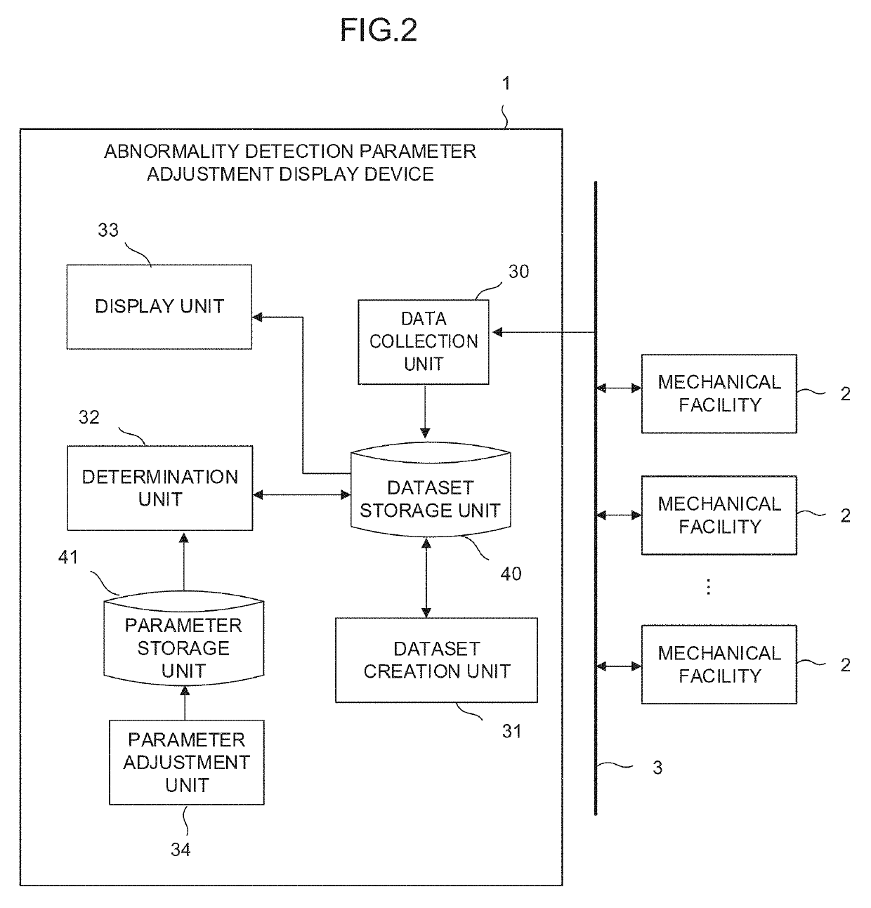
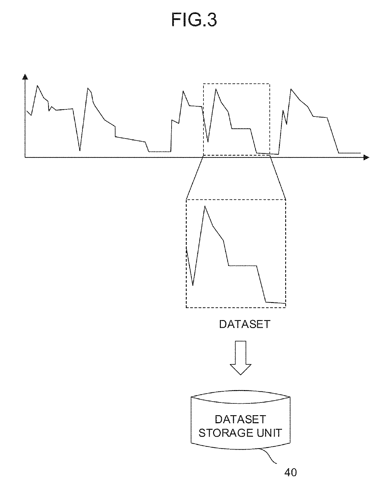
An abnormality detection parameter adjustment display device adjusts a parameter for determination for detecting operation abnormality of a mechanical facility based on an input from a user, collects operation information on the mechanical facility, creates a dataset based on the operation information, determines whether or not the dataset indicates a normal operating state, based on the parameter, displays the dataset in a graph, and makes an adjustment for display in such a position that the relationship between the data of the graph and the parameter is visually ascertainable.

Description

BACKGROUND OF THE INVENTIONField of the Invention[0001]The present invention relates to an abnormality detection parameter adjustment display device.Description of the Related Art[0002]Mechanical facilities, such as robots and machine tools, which operate in a factory are connected to a network for management. Devices connected to the network laid in the factory include, for example, a device that monitors the operating state of the entire factory, based on information on the mechanical facilities including the operating situations of the mechanical facilities connected to the network, a device that fixes operating schedules of the mechanical facilities based on production planning and personnel and facility information, and the like.[0003]Operation management software used to manage the operating situations of the mechanical facilities enables a user to set an arbitrary threshold for acquired signal data, thereby detecting failures caused in the mechanical facilities and issuing wa...

Claims


Application Information

Patent Timeline
IPC IPC(8): G06F3/0484
CPCG06F3/04847G06T11/206G06F11/321G05B19/406G06T11/203
Inventor UWANO, TOMOFUMI
Owner FANUC LTD
Learn More