Damping Valve For A Vibration Damper

a technology of vibration damper and damper, which is applied in the direction of shock absorber, vibration damper, spring/damper, etc., can solve the problem that the characteristic of stepped springs is appreciably more difficult to realize with precision in very small elastomer supports than can be achieved with precision, and achieve the effect of reducing the installation space requirement and facilitating assembly

Inactive Publication Date: 2019-07-25
ZF FRIEDRICHSHAFEN AG
View PDF4 Cites 0 Cited by
  • Summary
  • Abstract
  • Description
  • Claims
  • Application Information

AI Technical Summary

Benefits of technology

[0018]According to an advantageous subclaim, the two individual elastomer supports form a series arrangement with respect to the spring forces thereof. This construction facilitates assembly and in many cases reduces the installation space requirement.
[0019]With respect to a hydraulic damping force c

Problems solved by technology

Because of the limited installation space in a damping valve, the diameter of which amounts to between approximately 25 mm and approximately 40 mm, very small elastomer supports are also used, and

Method used


Image

  • Damping Valve For A Vibration Damper
  • Damping Valve For A Vibration Damper
  • Damping Valve For A Vibration Damper

Examples


Embodiment Construction

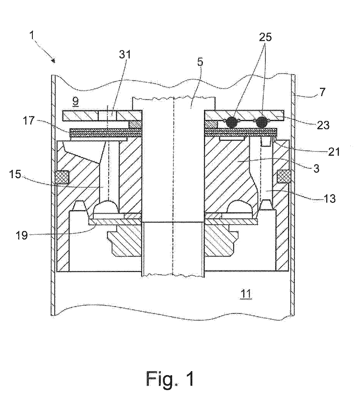
[0028]FIG. 1 shows a damping valve 1 for a vibration damper of any type of construction. Damping valve 1 comprises a damping valve body 3, which is fastened to a piston rod 5. The invention is not limited to an embodiment form of this type and can be used, e.g., in a bottom valve or also within the framework of an adjustable damping valve.

[0029]Damping valve body 3 divides a cylinder 7 of the vibration damper into a working chamber 9 on the piston rod side and a working chamber 11 remote of the piston rod 5. Both working chambers 9; 11 are filled with damping medium. Through-channels 13; 15, each for a flow direction, are formed on different pitch circles in damping valve body 3. The configuration of the through-channels is to be considered as exemplary only. An outlet side of through-channels 13; 15 is at least partially covered by at least one valve disk 17; 19.

[0030]When there is an incident flow against valve disk 17 proceeding from the working chamber 11 remote of the piston ro...


PUM


Abstract

A damping valve for a vibration damper, having a damping valve body with at least one through-channel, the outlet side of which is at least partially covered by at least one valve disk. The at least one valve disk lifts from a valve seat surface when there is an incident flow via the through-channel, and a supporting disk, as stop, limits the lift movement. The supporting disk is outfitted with an elastomer support in direction of the valve disk. The elastomer support is formed by a plurality of individual supporting elements. At least one individual supporting element is formed by at least two individual elastomer supports, which are paired to form an individual supporting element.

Description

CROSS REFERENCE TO RELATED APPLICATIONS[0001]This is a U.S. national stage of application No. PCT / EP2017 / 070445, filed on Aug. 11, 2017. Priority is claimed on German Application No. DE102016218375.3, filed Sep. 23, 2016, the content of which is incorporated herein by reference.BACKGROUND OF THE INVENTION1. Field of the Invention[0002]The invention is directed to a damping valve.2. Description of the Prior Art[0003]A damping valve for a vibration damper comprises a damping valve body with at least one through-channel, the outlet side of which is at least partially covered by at least one valve disk. When the valve side is impinged by flow via the through-channel, the valve disk lifts from a valve seat surface. To protect the valve disk from mechanical overload, at least one supporting disk is generally used as a stop, which limits the lift movement. In the simplest configuration, the supporting disk is constructed as a simple, generally metal, annular disk. In contrast, the valve di...

Claims


Application Information

Patent Timeline
IPC IPC(8): F16F9/348
CPCF16F9/3485
Inventor KNEZEVIC, ALEKSANDARROSSELER, JORG
Owner ZF FRIEDRICHSHAFEN AG
Why Eureka
Try Eureka