
Optical scanning device and image forming device

a scanning device and image technology, applied in the direction of electrographic process equipment, instruments, mountings, etc., can solve the problems of image deterioration risk, large vibration of deflecting mirrors, and large vibration of deflecting mirrors, and achieve high-quality dimensions

Active Publication Date: 2019-07-25
KONICA MINOLTA INC
View PDF2 Cites 0 Cited by
  • Summary
  • Abstract
  • Description
  • Claims
  • Application Information

AI Technical Summary

Benefits of technology

The present invention provides an optical scanning device and an image forming device that have a housing with very precise dimensions.

Problems solved by technology

The housing has a lowest rigidity around the center of the housing, and therefore when the deflector positioned near the center of the housing vibrates, the vibration tends to become large.
However, when the rotation speed of the deflecting mirror is increased, vibration of the deflecting mirror becomes larger.
Thus, if these contributing factors overlap, there is a risk of image deterioration due to a change in beam performance.
When the bottom plate 1331 of the housing 1330 warps, accuracy of dimensions of the housing 1330 cannot be ensured, and therefore misalignment can occur between the deflector and the optical element, and accurate beam performance on an image plane cannot be ensured.

Method used


Image

  • Optical scanning device and image forming device
  • Optical scanning device and image forming device
  • Optical scanning device and image forming device

Examples


Embodiment Construction

[0028]Hereinafter, embodiments of the present invention will be described with reference to the drawings. However, the scope of the invention is not limited to the disclosed embodiments.

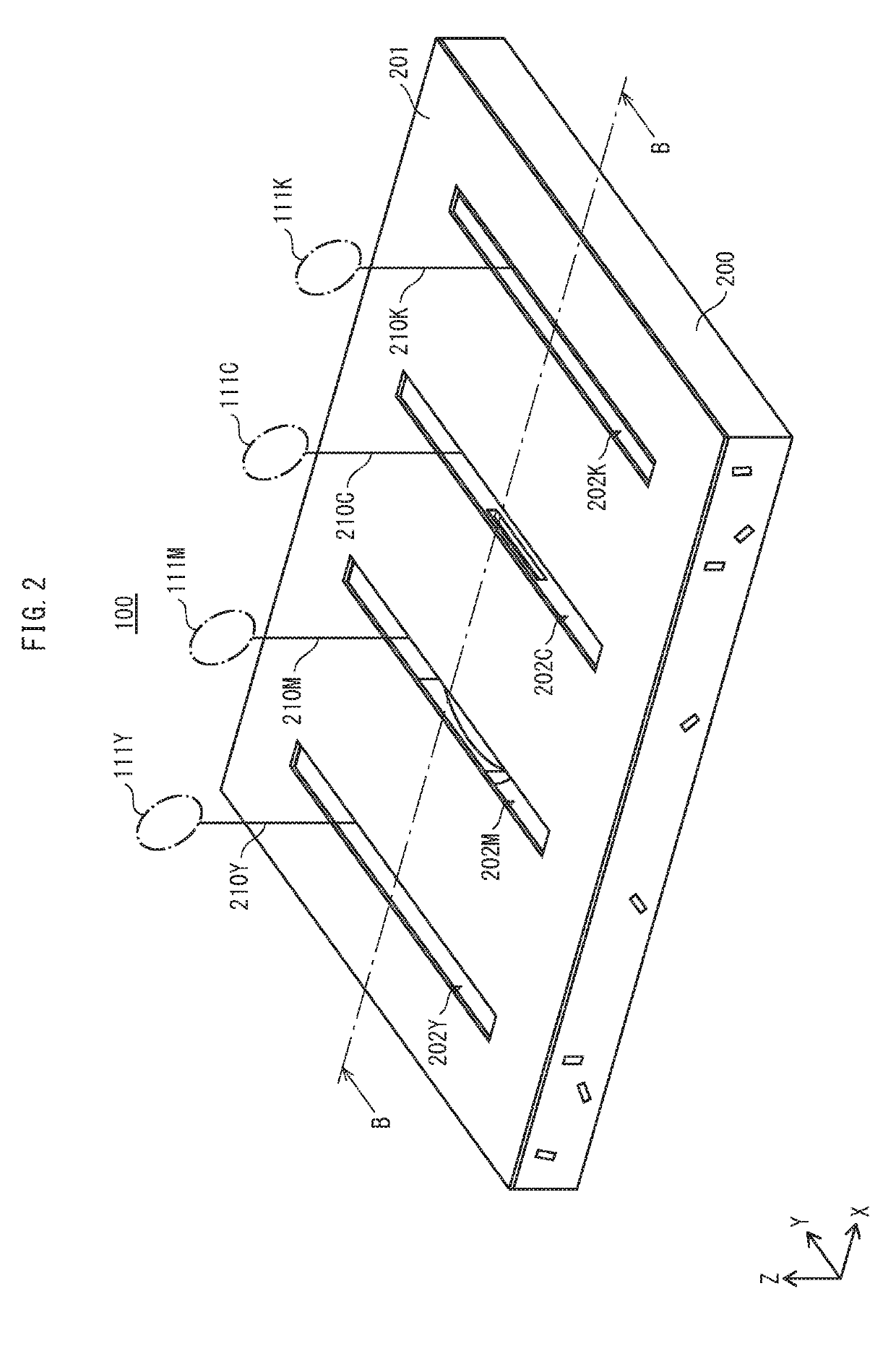
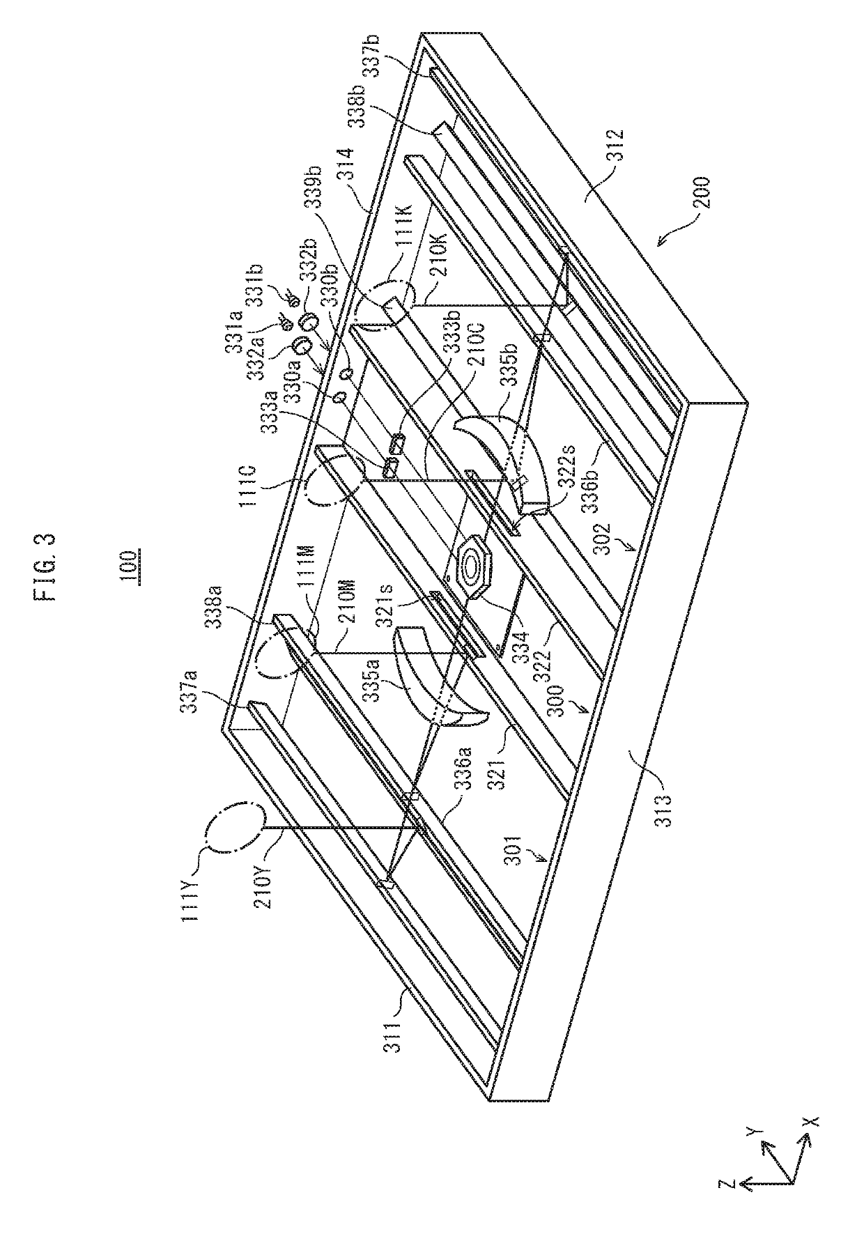
[0029]In an optical scanning device and image forming device pertaining to one or more embodiments of the present invention, a housing of the optical scanning device is partitioned by two ribs standing upright from a bottom plate, and a central portion of the bottom plate sandwiched between two ribs is higher than portions of the bottom plate to either side.

(1-1) Configuration of Image Forming Device

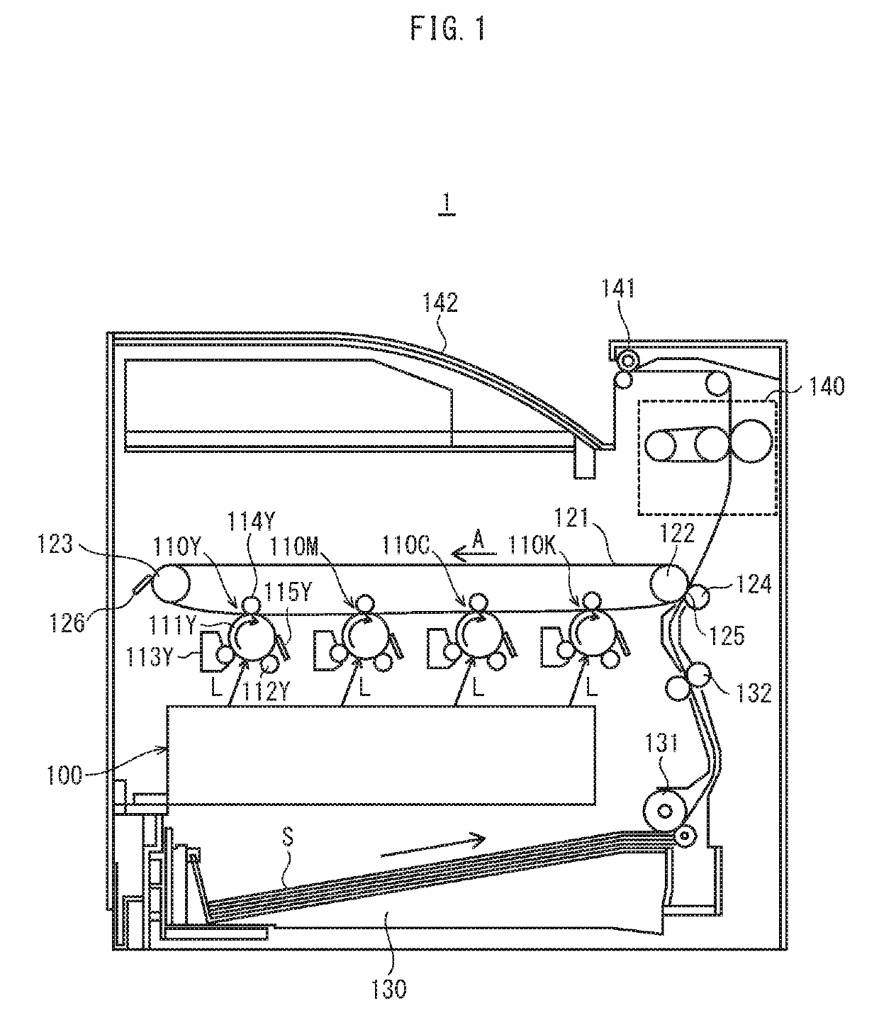
[0030]An image forming device pertaining to one or more embodiments is a tandem-type digital color printer that, when connected to a communication network such as a local area network (LAN) and upon receiving a print job from another device such as a personal computer (PC), forms toner images from yellow (Y), magenta (M), cyan (C), and black (K) toner, transfers the toner images, superimposing them to for...


PUM


Abstract

An optical scanning device including: a light source; a deflector that deflects light from the light source; an optical element that guides light deflected by the deflector on an optical path to a photosensor; and a housing that accommodates the deflector and the optical element. The housing is integrally formed and includes a bottom plate, a side wall standing upright from a periphery of a main surface of the bottom plate, and a pair of ribs parallel with each other and standing upright from the bottom plate. Both longitudinal ends of each of the ribs in plan view are joined to the side wall. A region of the bottom plate between the ribs in the plan view has a portion displaced farther upward in an upright direction of the side wall than other regions of the bottom plate.

Description

CROSS-REFERENCE TO RELATED APPLICATIONS[0001]This application claims priority to Japanese Patent Application No. 2018-010207 filed Jan. 25, 2018, the contents of which are hereby incorporated herein by reference in their entirety.BACKGROUND[0002]The present invention relates to optical scanning devices and image forming devices, and in particular to techniques for suppressing warping of housings in optical scanning devices.[0003]Among electrophotographic image forming devices are image forming devices that use an optical scanning device to form an electrostatic latent image through exposure of a photoreceptor. An optical scanning device scans a photoreceptor surface with a laser beam by deflecting the laser beam emitted from a laser diode (LD), by using a deflecting mirror and an optical element housed in a housing. The deflecting mirror is held by a deflector, and the deflector is generally positioned near a center of the housing.[0004]The deflector drives the deflecting mirror to ...

Claims


Application Information

Patent Timeline
Patent Type & Authority Applications(United States)
IPC IPC(8): G03G15/04G02B26/12
CPCG03G15/04036G02B26/123G03G15/04G02B7/028
Inventor SAITO, SHINYAHASEGAWA, RYOTANIGUCHI, HAJIME
Owner KONICA MINOLTA INC
Learn More