Unmanned aerial vehicle detection system and unmanned aerial vehicle detection method

a technology for unmanned aerial vehicles and detection systems, which is applied in the field of unmanned aerial vehicle detection systems and unmanned aerial vehicle detection methods, can solve the problems of difficult to grasp an existence and difficult to easily grasp the position of unmanned aerial vehicles from surrounding circumstances, and achieve the effect of easy determination of existen

Inactive Publication Date: 2019-07-25
PANASONIC INTELLECTUAL PROPERTY MANAGEMENT CO LTD
View PDF0 Cites 16 Cited by
  • Summary
  • Abstract
  • Description
  • Claims
  • Application Information

AI Technical Summary

Benefits of technology

[0010]According to the present disclosure, it is possible to easily determine an existence and a position of an unmanned aerial vehicle desired by a user by using a captured image by a camera.

Problems solved by technology

In this case, it is difficult to grasp an existence of an unmanned aerial vehicle desired by a user and even if an unmanned aerial vehicle exists, it is also difficult to easily grasp a position of the unmanned aerial vehicle form surrounding circumstances.

Method used


Image

  • Unmanned aerial vehicle detection system and unmanned aerial vehicle detection method
  • Unmanned aerial vehicle detection system and unmanned aerial vehicle detection method
  • Unmanned aerial vehicle detection system and unmanned aerial vehicle detection method

Examples


first exemplary embodiment

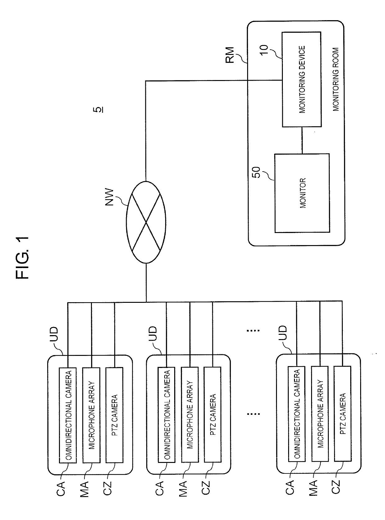
[0046]FIG. 1 is a diagram showing an example of a schematic configuration of unmanned aerial vehicle detection system 5 according to a first exemplary embodiment. Unmanned aerial vehicle detection system 5 detects unmanned aerial vehicle dn (see FIG. 14, for example) desired by a user as a detection target. Unmanned aerial vehicle dn is a multicopter such as a UAV (for example, drone) autonomously flying using a global positioning system (GPS) function, a radio-controlled helicopter that is wirelessly controlled by a third party, or the like. Such unmanned aerial vehicle dn is used for, for example, aerial photographing of a target, spraying of liquid such as agricultural chemicals, transportation of goods, or the like.

[0047]In the present exemplary embodiment, a multicopter type drone having a plurality of rotors (in other words, rotating blades) mounted on is exemplified as unmanned aerial vehicle dn. In a multicopter type drone, in general, when the number of wings of a rotor is ...

first modification example of first embodiment

[0157]FIG. 16 is a diagram showing an example of a schematic configuration of unmanned aerial vehicle detection system 5A according to a first modification example of the first exemplary embodiment. In the first exemplary embodiment, the camera disposed on the same axis as microphone array MA is omnidirectional camera CA, but in the first modification example of the first exemplary embodiment (hereinafter referred to as “first modification example”), fixed camera CF is disposed so as to coincide with a center axis of microphone array MA and its own optical axis.

[0158]Fixed camera CF is a camera having a predetermined angle of view with an optical axis fixed in a specific direction, and is installed in advance so as to be able to image, for example, a space expected to fly by unmanned aerial vehicle dn. Here, angle of view ag1 of fixed camera CF is set above building group bLg.

[0159]When unmanned aerial vehicle dn is detected, a camera that changes an imaging direction to a direction...

second modification example of first exemplary embodiment

[0165]FIG. 17 is a diagram showing an example of a schematic configuration of unmanned aerial vehicle detection system 5B according to a second modification example of the first exemplary embodiment. In the first exemplary embodiment, the camera disposed on the same axis as microphone array MA is omnidirectional camera CA, and in the first modification example, the camera disposed on the same axis as microphone array MA is fixed camera CF. In the second modification example of the first exemplary embodiment (hereinafter referred to as “second modification example”), PTZ camera CZ1 is disposed so as to coincide with a center axis of microphone array MA and its own optical axis.

[0166]PTZ camera CZ1 is a camera capable of imaging by changing a direction of an optical axis, and capable of imaging by changing an angle of view in a stepwise manner in a predetermined direction (preset direction) with respect to monitoring area 8 (see FIG. 11) which is a half celestial sphere. For example, ...


PUM


Abstract

In an unmanned aerial vehicle detection system, an omnidirectional camera images a monitoring area. A microphone array picks up a sound in the monitoring area. A monitoring device detects an unmanned aerial vehicle appearing in the monitoring area using the sound data picked up by the microphone array. When displaying image data of the monitoring area captured by the omnidirectional camera on a monitor, a signal processor in the monitoring device superimposes an identification mark obtained by converting the unmanned aerial vehicle into visual information on the image data of the monitoring area.

Description

TECHNICAL FIELD[0001]The present disclosure relates to an unmanned aerial vehicle detection system and an unmanned aerial vehicle detection method for detecting an unmanned aerial vehicle (UAV).BACKGROUND ART[0002]A flying object monitoring device has been known that is capable of detecting an existence of an object and detecting a flying direction of the object using a plurality of sound detectors that detect sounds generating within a monitoring area for each direction. (see PTL 1, for example). When detecting a flying and a flying direction of the flying object by a sound detection using a microphone, a processing device of the flying object monitoring device moves a monitoring camera in the direction in which the flying object flew. The processing device displays an image captured by the monitoring camera on a display device.[0003]However, for example, in an image captured by the monitoring camera, various flying objects other than an unmanned aerial vehicle desired by a user ma...

Claims


Application Information

Patent Timeline
Patent Type & Authority Applications(United States)
IPC IPC(8): G08G5/00B64C39/02H04N7/18H04R3/00
CPCG08G5/0082B64C39/024H04N7/181H04R3/005H04R2499/13B64F1/36B64F3/00G08G5/0026G08G5/0069H04N7/188H04R1/028
Inventor MATSUMOTO, HIROYUKIYOSHIKUNI, SHINTAROYUGE, RYOICHI
Owner PANASONIC INTELLECTUAL PROPERTY MANAGEMENT CO LTD
Why Eureka
Try Eureka