
High reliability hybrid energy storage system

a hybrid energy storage and high reliability technology, applied in parallel/serial switching, electrochemical generators, battery/cell propulsion, etc., can solve the problems of a large amount of short-term power draw from the grid, fuel cells are typically high in energy density and low in power density when compared, and the process is relatively time-consuming and laborious

Active Publication Date: 2019-07-25
ELECTRIC POWER SYSTEMS INC
View PDF0 Cites 10 Cited by
  • Summary
  • Abstract
  • Description
  • Claims
  • Application Information

AI Technical Summary

Benefits of technology

The present invention relates to energy storage systems for electric vehicles, particularly in the form of fuel cell stacks combined with battery cells to provide the necessary power and energy for propulsion. The technical effects of this invention include higher energy density and power density, as well as improved recharging methods for fuel cells. By incorporating both fuel cells and batteries in an energy storage system, the system can provide more power and energy for longer ranges of electric vehicles. Additionally, the use of larger cells or cells in parallel can increase the power level of the battery or fuel cell system, further increasing the energy density and power density.

Problems solved by technology

Fuel cells are typically high in energy density and low in power density when compared to batteries.
Energy expended by a battery is replaced by direct electrical recharging, which is a relatively time consuming process, often requiring one or more hours to complete.
However, this rate of recharge requires a large battery charger and draws a great deal of short-term power from the grid.
Such short-term power demands often come at a higher price, since the cost of electricity is impacted by the rate of draw.
In widespread application, this can cause stability problems with the grid, something that the utility providers deem highly undesirable.
Adding batteries to the charging system can stabilize the load, but comes at great cost since these batteries must have as much capacity as required to meet the constant recharge demands for the application.
Further, such a battery will have to be replaced over time as it ages and loses capacity due to cycle degradation.
In contrast, fuel cells require a warming period of time, and therefore very little operating power is immediately available.
This is problematic in most traction applications, especially vehicles used for transportation.
The relatively large number of fuel cells that must be assembled into a stack also impacts the overall system performance and cost.
This is also complicated by the need for isolation management as the voltage potential increases in order to maintain safety, complicated further by the continuous presence of water as the exhaust component of the system that must be safely removed during operation.
As such, the majority of fuel cell systems produced are relatively low voltage, too low for typical industry standard traction systems.
DC-DC converters add losses, additional mass, and cost to the system.
The DC-DC converter does not add any benefit to the system other than the conversion of voltage.
It adds parasitic weight, space, and cost, and is especially impactful in aviation applications that are extremely weight sensitive.
Such a solution would also require a substantial amount of volume and a cooling system for the converter, adding more mass to the system.
The DC-DC converters do not contribute anything to alleviating the single point of failure in the system since they are not themselves energy sources, only energy converters with parasitic loads as their price to operate.
As the fuel cell stack is often the most expensive component in the system, acquiring two would be a very substantial cost impact to the application.

Method used


Image

  • High reliability hybrid energy storage system
  • High reliability hybrid energy storage system
  • High reliability hybrid energy storage system

Examples


Embodiment Construction

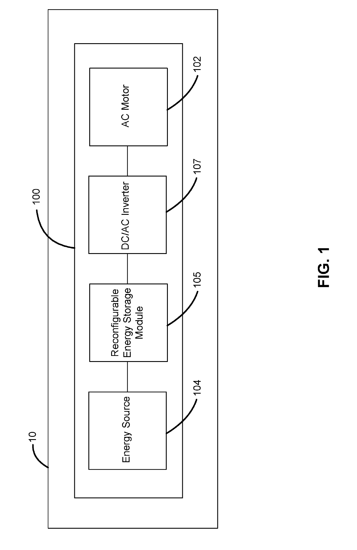
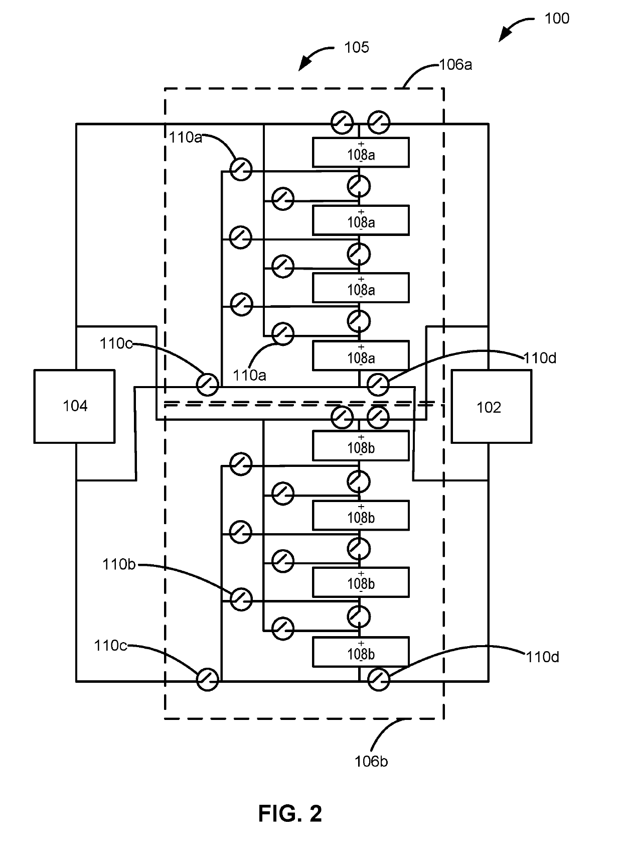
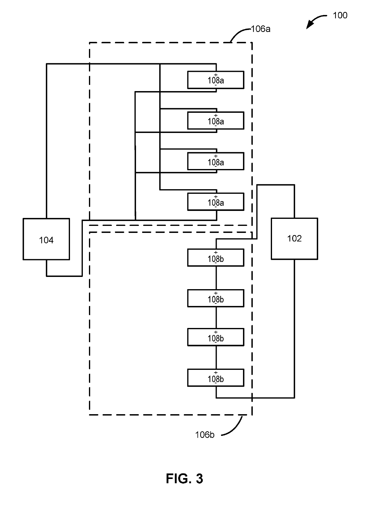
[0024]The present description provides novel systems and methods of using cost-effective, low-voltage fuel cell systems in weight sensitive, high reliability, high efficiency, high voltage traction applications by utilizing a switch mode battery system. The approach increases reliability, adds redundancy, and minimizes parasitic components such as DC-DC converters that add weight, reduce reliability, and increase system losses.

[0025]With initial reference to FIG. 1, an aircraft 10 comprises an energy storage and power delivery system 100. In various embodiments, aircraft 10 comprises an unmanned aerial vehicle caused to be moved by one or more traction motors. In other embodiments, aircraft 10 can be a passenger or cargo aircraft or a helicopter powered by one or more traction motors. Moreover, aircraft 10 may comprise any suitable vehicle that is caused to move, in whole or in part, by an asynchronous motor or A / C motor. Although described herein in connection with aircraft, this d...


PUM

PropertyMeasurementUnit
voltageaaaaaaaaaa
voltageaaaaaaaaaa
voltageaaaaaaaaaa

Abstract

Combination fuel cell stack and electrochemical battery system provides stable and redundant electrical power to one or more traction motors. The electrochemical battery packs comprise modules that are switched between a low-voltage parallel configuration connecting to the fuel cell stack and a high-voltage series configuration connecting to the traction motors, thereby harvesting low-voltage energy from the fuel cells and deploying that energy as high-voltage power to the motor. The plurality of electrochemical battery packs can be switched such that at least one is always connected to the traction motor for continuity of power.

Description

CROSS REFERENCE TO RELATED APPLICATIONS[0001]This application claims priority to U.S. Provisional Application Ser. No. 62 / 399,746 filed on Sep. 26, 2016, the disclosure of which, is incorporated herein by reference to the extent such disclosure does not conflict with the present disclosure.TECHNICAL FIELD OF THE INVENTION[0002]The present invention relates generally to energy storage systems for electric vehicles, such as aircraft, and more specifically, for energy storage systems utilizing fuel cell stacks combined with batteries to provide appropriate voltage to electric motors of electric vehicles.BACKGROUND OF THE INVENTION[0003]A secondary battery is a device consisting of one or more electrochemical or electrostatic cells, hereafter referred to collectively as “cells,” that can be charged electrically to provide a static potential for power or released electrical charge when needed. Electrochemical cells typically comprise at least one positive electrode and at least one negat...

Claims


Application Information

Patent Timeline
Patent Type & Authority Applications(United States)
IPC IPC(8): H02J7/00H02J1/06H01M16/00B64C39/00
CPCH02J7/0024H02J1/06H02J7/0065H01M16/006B64C39/00H02J2001/004B64C2201/042H02J2300/30H02J7/34H02J2310/48B64U50/19B64U50/30H02J2207/20Y02T10/70Y02E60/10Y02E60/50H02J7/342B60L50/64
Inventor DUNN, RANDY B.HORN, ALAN
Owner ELECTRIC POWER SYSTEMS INC
Learn More