

Piston groove machining tool
- Summary
- Abstract
- Description
- Claims
- Application Information
AI Technical Summary
Benefits of technology
Problems solved by technology
Method used
Image

Examples
Embodiment Construction
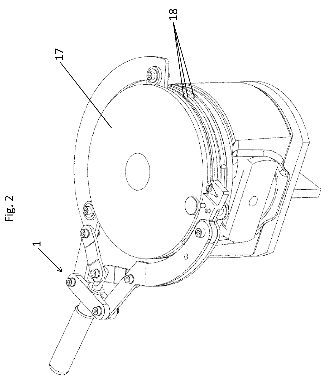
[0029]In the figures shown, the rotation-symmetric component to be machined is designed in an exemplary manner as piston 17 with at least one piston groove 18 to be cleaned.
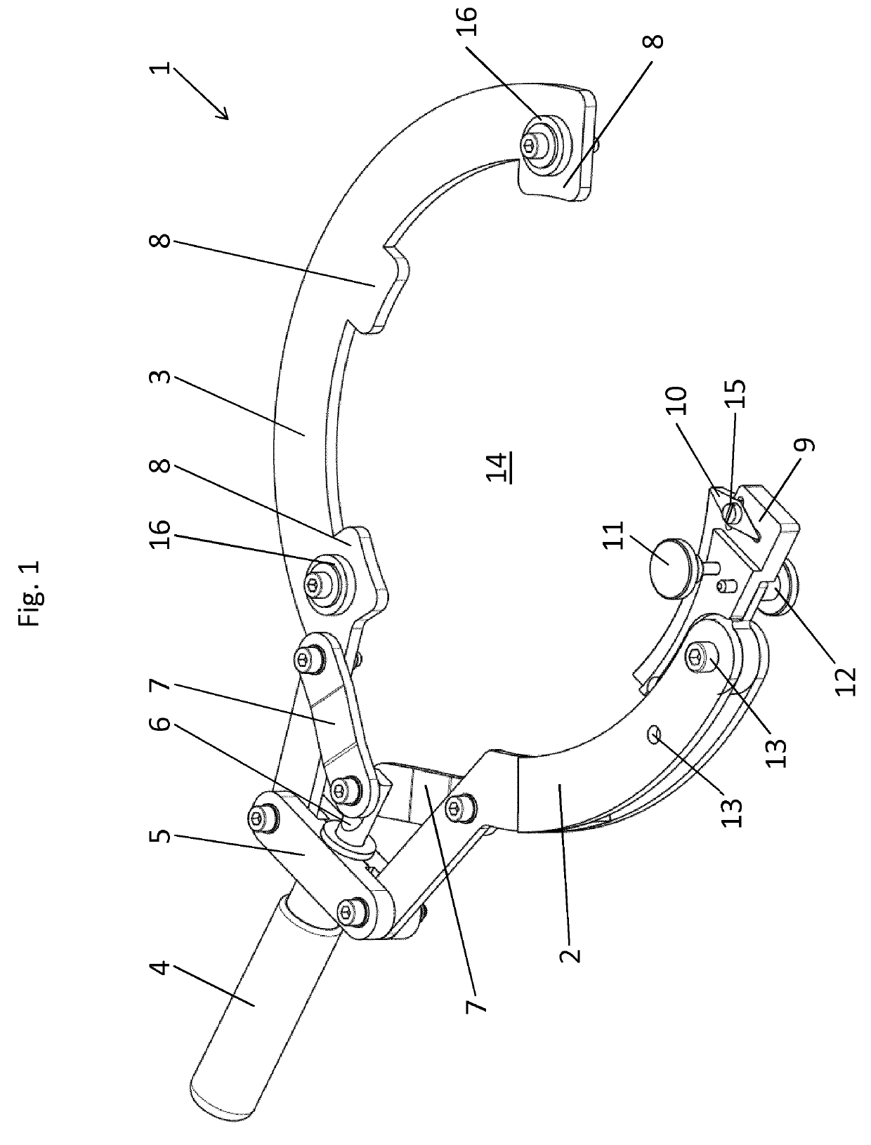
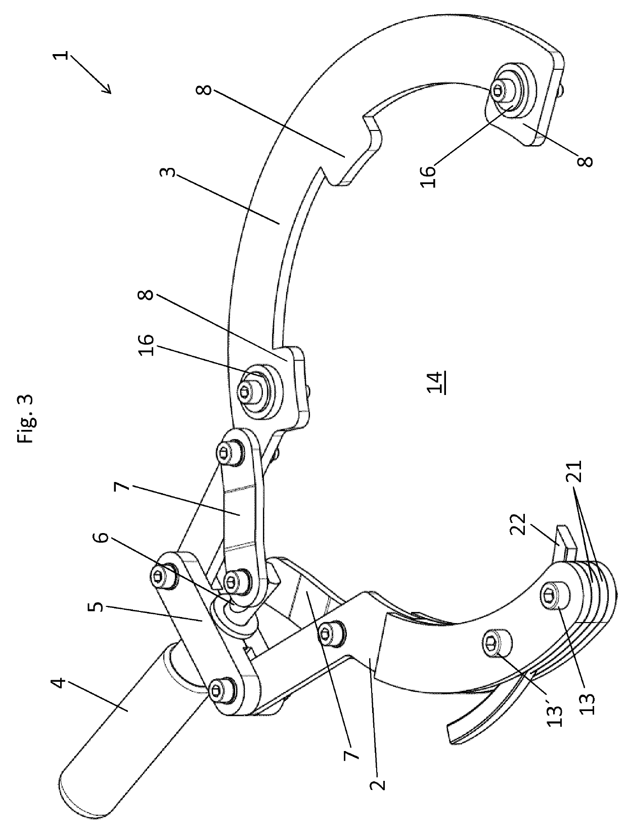
[0030]FIG. 1 shows a perspective view of an exemplary embodiment of a tool 1 with a first arm 2 and a second arm 3 and a handle 4 according to the disclosure. For the machining of a piston groove 18 of a piston 17 (see FIG. 2) the tool 1 is manually guided by means of the handle 4 once or several times around the piston 17.
[0031]On the first arm 2 (in the area of the free end of the first arm 2), a holder 9 is detachably mounted by the fastening element 13, which in the state shown carries a cutting tool 10 (hereinafter referred to as “cutting blade”) for the machining of the groove flanks of a selected piston groove 18 of a piston 17.
[0032]A guiding device is disposed on the second arm 2, which is here designed in the form of three guiding elements 8 distributed over the length of the second arm 2 and two guide ...
PUM
| Property | Measurement | Unit |
|---|---|---|
| Force | aaaaa | aaaaa |
| Diameter | aaaaa | aaaaa |
| Circumference | aaaaa | aaaaa |
Abstract
Description
Claims
Application Information