Supercharge Your Innovation With Domain-Expert AI Agents!

Intelligent label device and method

a technology of intelligent labels and labels, applied in the field of intelligent labels, can solve the problems of product spoilage or otherwise unusable, and achieve the effects of reliable time determination, accurate and traceable time, and robustness

Active Publication Date: 2019-08-01
CHROMERA
View PDF2 Cites 2 Cited by
  • Summary
  • Abstract
  • Description
  • Claims
  • Application Information

AI Technical Summary

Benefits of technology

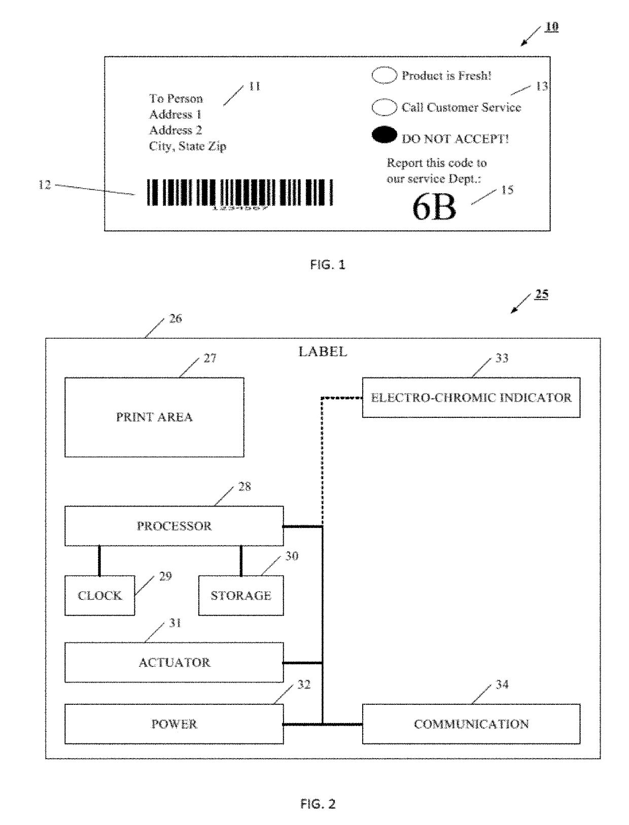
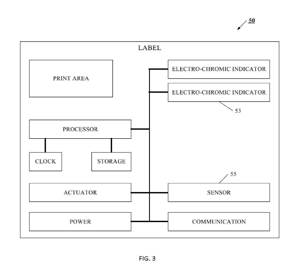
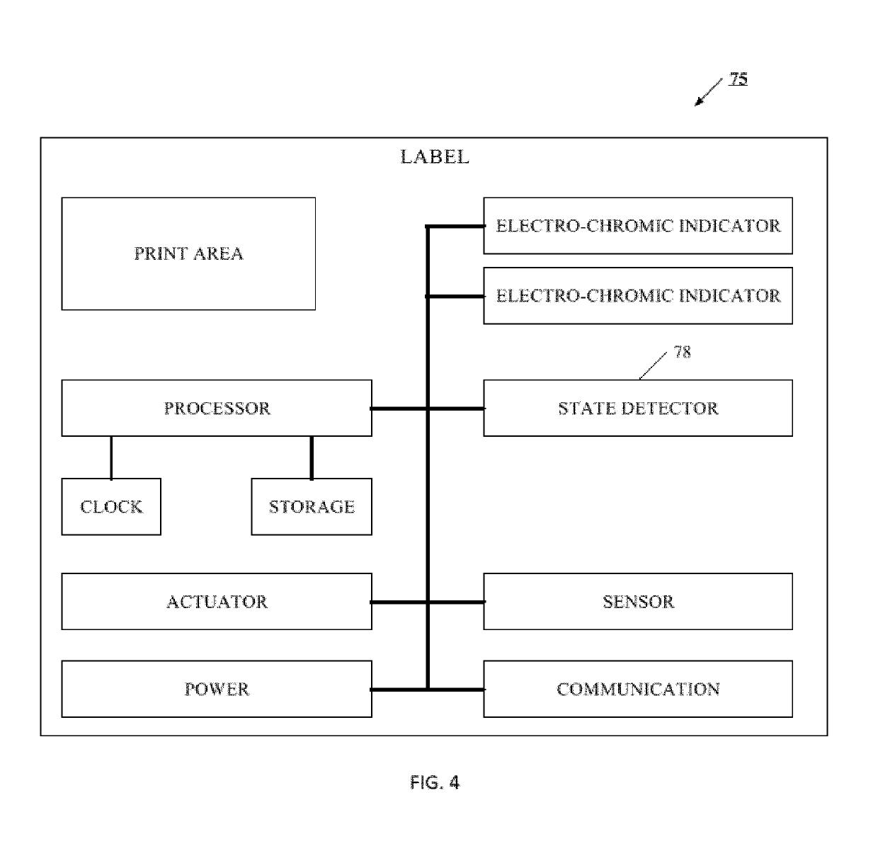
The patent describes an intelligent label that can be used to track and monitor the condition of a good from the time it is placed in the shipping chain until it is delivered to the consumer. The label contains permanent and irreversible electrochromic indicators that provide visual information without the need for expensive communication or interrogation equipment. The label can be attached to the good in various forms, such as a tag or integrated into the packaging or good itself. It can also include print information, usage rules, or address and coded information. The label has an actuator that can determine the time it was attached to the good, which helps in accurately tracking the good through the shipping chain. The label helps create a trustworthy and easily usable system for shipping and delivery, providing valuable feedback without compromising the privacy and security of the shipping process.

Problems solved by technology

In another example, the processor may determine that the sensor has greatly exceeded the outer specification criteria, and cause an electrochromic indicator to show that the product is spoiled or otherwise unusable.

Method used


Image

  • Intelligent label device and method
  • Intelligent label device and method
  • Intelligent label device and method

Examples


example 2

[0111] Preparation of an EC indicator with clear electrolyte. To a small sure seal bottle was added 0.3 g of PMMA (15,000 average molecular weight) and 0.733 ml of acetonitrile and ionic liquid (0.49 g of 1-Butyl-1-methylpyrrolidinium bis(trifluoromethylsulfonyl)imide. This was sealed and stirred for one hour to form a solution. To this was added 0.15 g of PMMA to give a total of 0.45 g of polymer. The mixture was stirred for two hours to form a solution. 0.033 g of fumed silica was added and again stirred for one hour. The bottle was placed in a fume hood under an argon atmosphere and 2-2′ bithiophene (0.041 g) and the lithium salt [HQ-115, Lithium Bis(trifluoromethanesulfonyl)imide, 0.14 g] were added. The flask was sealed and stirred for one hour to form a light green solution which after stirring for 24 hours turned dark green. Its viscosity was 87 centipoise, measured using Brookfield Model DV-III+ programmable viscometer at a shear strain of 960 s-1. This electrolyte was used ...

example 3

[0113] EC indicator with opposing interdigitated electrodes on the same substrate. A transparent electrolyte was prepared by mixing 0.45 g of PMMA (15K MW), 0.033 g of fumed silica and 0.563 g of anhydrous acetonitrile. The mixture was stirred at 25° C. for two hours to form a translucent solution. Under an inert atmosphere was added 0.041 g of 2,2′ bithiophene, 0.014 g of lithium bis(trifluoromethanesulfonyl)imide and 0.8 g of 1methyl-1butylpyrrolidinum bis(trifluoromethanesulfonyl)imide. The mixture after stirring for two hours had a light green color.

[0114]A device was fabricated as described in Example 2 except that a patterned ITO electrode was used. The pattern was made using a laser etching process. In this process the ITO was etched from the substrate using an IR laser, where the width of the etched (or ablated) line was in the range of 30 to 50 microns. One could have also used UV or visible region lasers with etched widths down to less than 10 microns. A schematic drawing ...


PUM


Abstract

Briefly, an intelligent label is associated with a good, and includes one or more permanent and irreversible electrochromic indicators that are used to report the condition of that good at selected points in the movement or usage of that good. These electrochromic indicators provide immediate visual information regarding the status of the good without need to interrogate or communicate with the electronics or processor on the intelligent label. In this way, anyone in the shipping or use chain for the good, including the end user consumer, can quickly understand whether the product is meeting shipping and quality standards. If a product fails to meet shipping or quality standards, the particular point where the product failed can be quickly and easily identified, and information can be used to assure the consumer remains safe, while providing essential information for improving the shipping process. It will be understood that the label may take many forms, such as a tag attached to the good, integrated into the packaging for the good, integrated into the good itself, or may even be an information area on a prepaid card for example. The label may also include, for example, print information regarding the good, usage or shipping rules, or address and coded information.

Description

RELATED APPLICATIONS[0001]This application is a continuation of U.S. patent application Ser. No. 15 / 268,942, filed Sep. 19, 2016, which is a continuation of U.S. patent application Ser. No. 14 / 479,055, filed Sep. 5, 2014, and now issued as U.S. Pat. No. 9,471,862, which claims priority to provisional application Ser. No. 61 / 922,060, filed Dec. 30, 2013; provisional application Ser. No. 61 / 955,235, filed Mar. 19, 2014; provisional application Ser. No. 61 / 955,236, filed Mar. 19, 2014; provisional application Ser. No. 61 / 955,237, Mar. 19, 2014; provisional application Ser. No. 61 / 975,112, filed Apr. 4, 2014; provisional application Ser. No. 62 / 025,043, filed Jul. 16, 2014; and provisional application Ser. No. 62 / 025,045, filed Jul. 16, 2014. This application is also a continuation-in-part to U.S. patent application Ser. No. 14 / 679,213, filed Apr. 6, 2015, which is a divisional application to U.S. patent application Ser. No. 13 / 002,275, Entitled Flexible and Printable Electrooptic Devic...

Claims


Application Information

Patent Timeline
Patent Type & Authority Applications(United States)
IPC IPC(8): G06K19/07G06K7/10G06K19/06G06K19/077
CPCG06K19/0717G06K7/10366G06K19/06028G06K19/0723G06K19/0702G06K19/07707G06K19/0776
Inventor ATKINSON, PAULKRUEST, JAMESAGRAWAL, ANOOPCRONIN, JOHN P.ADAMS, LORI LTONAZZI, JUAN CARLOS L
Owner CHROMERA
Features
  • R&D
  • Intellectual Property
  • Life Sciences
  • Materials
  • Tech Scout
  • Unparalleled Data Quality
  • Higher Quality Content
  • 60% Fewer Hallucinations
Learn More