Power storage device cooling structure

a technology of power storage devices and cooling structures, which is applied in the direction of electrochemical generators, cell components, batteries, etc., can solve the problems of pressure loss, difficulty in inserting an end portion of the air intake duct into some of the plurality of coupling portions of the housing case, etc., to reduce defective assembly, eliminate processing, and high precision

Active Publication Date: 2019-08-01
TOYOTA JIDOSHA KK
View PDF0 Cites 1 Cited by
  • Summary
  • Abstract
  • Description
  • Claims
  • Application Information

AI Technical Summary

Benefits of technology

[0007]According to this configuration, the battery module's side and the distribution duct can be positioned by the insertion structure. The planar sealing structure allows a distribution path and the battery module to be connected over an increased area and can thus absorb a tolerance of a component in both a heightwise direction and a widthwise direction and hence reduce defective assembling of the distribution duct to the battery module.
[0008]In the above power storage device cooling structure, the plurality of distribution paths may have only one thereof connected to the ventilation path by the insertion structure. This is advantageous in terms of production because it can eliminate the necessity of processing with high precision a distribution path connected by the planar sealing structure.
[0009]In the above power storage device cooling structure, a path that would have a largest pressure loss if the plurality of distribution paths had all been connected to the ventilation paths via the planar sealing structure may be connected by the insertion structure. By applying the insertion structure to a path having a large pressure loss, a distribution path can be designed to have an appropriate shape to effectively reduce a pressure loss.
[0010]In the above power storage device cooling structure, the first distribution path connected via the insertion structure may have a portion having a cross-sectional area larger than a cross-sectional area of an outlet of the second distribution path connected via the planar sealing structure. The distribution path having an increased cross-sectional area to widen a flow path through the distribution path for refrigerant can reduce a flow rate of the refrigerant passing through the distribution path, and hence a pressure loss.
[0011]In the above power storage device cooling structure, the portion having the larger cross-sectional area may be a bent duct portion which is a bent portion of a duct forming the first distribution path. The distribution path thus formed can have an increased cross-sectional area to reduce a pressure loss and suppress a pressure loss otherwise increased as a flow of refrigerant passing through the bent duct portion would separate.

Problems solved by technology

In that case, it may be difficult to insert an end portion of the air intake duct into some of the plurality of coupling portions of the housing case.
The distribution path having an increased cross-sectional area to widen a flow path through the distribution path for refrigerant can reduce a flow rate of the refrigerant passing through the distribution path, and hence a pressure loss.

Method used


Image

  • Power storage device cooling structure
  • Power storage device cooling structure
  • Power storage device cooling structure

Examples


Embodiment Construction

[0019]Hereinafter, a structure to cool a power storage device in an embodiment will be described with reference to the drawings. In the following embodiment, any identical or substantially identical configuration is identically denoted and will not be described redundantly.

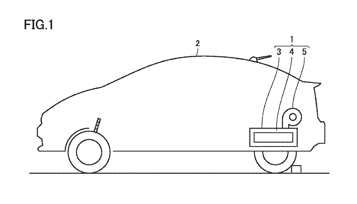
[0020]FIG. 1 is a schematic diagram showing a vehicle 2 with a power storage device 1 mounted therein. As shown in FIG. 1, vehicle 2 includes power storage device 1 disposed therein. Vehicle 2 with power storage device 1 mounted therein may be a hybrid vehicle capable of traveling using power of at least one of a motor and an engine, or an electric vehicle which is driven by force obtained through electrical energy.

[0021]Power storage device 1 includes a battery case 3, a battery unit 4, and a fan 5. Battery unit 4 is accommodated in battery case 3. Fan 5 supplies an interior of battery case 3 with the air inside the passenger compartment.

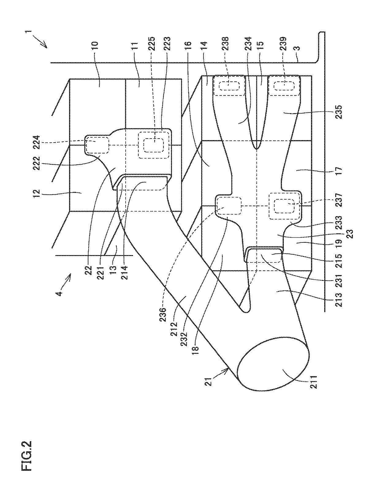
[0022]FIG. 2 is a schematic perspective view of power storage device 1. As s...


PUM

PropertyMeasurementUnit
diameteraaaaaaaaaa
pressure lossaaaaaaaaaa
areaaaaaaaaaaa

Abstract

Defective assembling of a duct to a battery module is reduced. A distribution duct has a plurality of distribution paths supplying refrigerant to each of a plurality of ventilation paths. A distribution path and a ventilation path are connected by an insertion structure in which the distribution path is inserted into the ventilation path. A distribution path has an open outlet end surrounded by a coupling portion, and is connected to a ventilation path via a planar sealing structure in which a sealing material is held on the coupling portion in a compressed state.

Description

[0001]This nonprovisional application is based on Japanese Patent Application No. 2018-014580 filed on Jan. 31, 2018 with the Japan Patent Office, the entire contents of which are hereby incorporated by reference.BACKGROUNDField[0002]The present disclosure relates to a power storage device cooling structure.Description of the Background Art[0003]Conventionally, an in-vehicle battery including a plurality of battery modules each having a plurality of battery cells disposed therein and a housing case for housing the plurality of battery modules comprises an air intake duct for blowing air into the plurality of battery modules to cool them, for example as disclosed in Japanese Patent Laying-Open No. 2016-132314.SUMMARY[0004]In the configuration described in the above document, the air intake duct has a plurality of end portions respectively inserted into and coupled to a plurality of coupling portions protruding from a side surface of the housing case to form an inflow path for the coo...

Claims


Application Information

Patent Timeline
Patent Type & Authority Applications(United States)
IPC IPC(8): H01M10/613H01M2/10H01M10/625H01M10/6557H01M10/6563H01M10/6566H01M50/204
CPCH01M10/613H01M2/10H01M10/625H01M10/6557H01M10/6563H01M10/6566H01M2220/20B60K11/06H01M10/6567H01M10/6556H01M50/204Y02E60/10
Inventor KOBAYASHI, TAKENORIIWASE, IKKO
Owner TOYOTA JIDOSHA KK
Why Eureka
Try Eureka