Water conservating silt discharging device

Active Publication Date: 2019-08-08
LIU XIAOJUN
View PDF1 Cites 8 Cited by
  • Summary
  • Abstract
  • Description
  • Claims
  • Application Information

AI Technical Summary

Benefits of technology

The present invention is a water-conserving device for treating silt. It has a moving bottom plate and a conveyor system for conveying silt material to a stirring box, which uses a jitter mechanism to remove impurities. The silt is then filtered and compressed by a compression box before being discharged. The device has a reasonable design and is easy to use, making it suitable for widespread promotion. Overall, it effectively improves the quality of silt treatment.

Problems solved by technology

If the sediment or silt is not cleaned regularly, it will easily lead to blockage of waterways and livers, which greatly affects water conservation facilities.
In order to clean up the sediment and the silt, some methods directly used manual excavation, but these methods are not only time-consuming and labor-intensive, but they also easily affect the ecology of the river.
However, due to the limitations of the prior structure and design of silt discharging devices, they are often unable to filter muddy water and mixed impurities in the silt during the process of extracting the silt, thereby greatly reducing the silt treatment quality and affecting performance of the silt discharging, device.

Method used


Image

  • Water conservating silt discharging device
  • Water conservating silt discharging device

Examples


Embodiment Construction

[0007]To make the objects, technical proposals and merits of the present disclosure more apparent, the present disclosure will be further described in detail with reference to the drawings and embodiments. It should be understood that the embodiments described here are only used to illustrate the present disclosure and are not intended to limit the present disclosure.

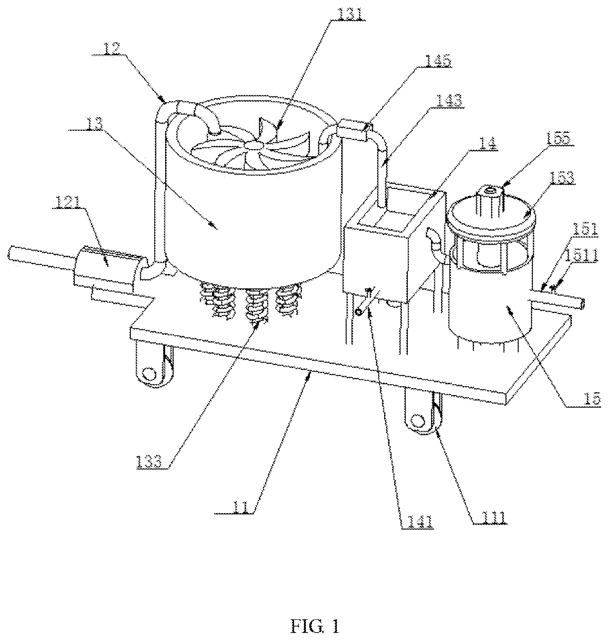
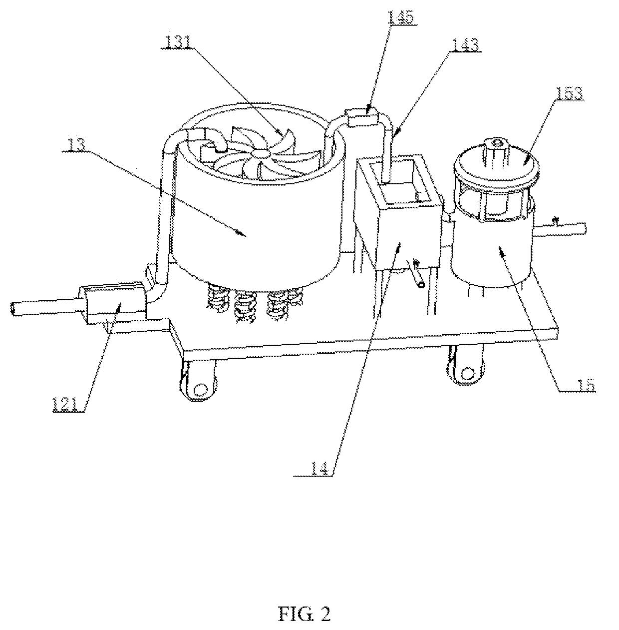
[0008]As shown in FIG. 1 and FIG. 2, the present disclosure provides a water conserving silt discharging device 1 for effectively improving silt treatment quality The water conserving silt discharging device 1 comprises a moving bottom plate 11. A first material conveying water pump 121, a stirring box 13, a filter box 14 and a compression box 15 are sequentially arranged on an upper portion of the moving bottom plate 11. A roller mechanism 111 is arranged on each of four diagonal portions of a lower portion of the moving bottom palate 11. A controller, an infrared sensor, and a high-definition camera assembly are arran...


PUM

PropertyMeasurementUnit
Lengthaaaaaaaaaa
Lengthaaaaaaaaaa
Lengthaaaaaaaaaa

Abstract

A water conserving silt discharging device includes a moving bottom plate. A first material conveying water pump, a stirring box, a filler box and a compression box are sequentially arranged on an upper portion of the moving bottom plate. And a roller mechanism is arranged on each of four diagonal portions of a lower portion of the moving bottom palate. A controller, an infrared sensor and a high-definition camera assembly are arranged on the upper portion of the moving bottom plate. The first material conveying water pump conveys silt material to the stirring box through a convey pipe. A jitter mechanism assembly is arranged at a bottom portion of the stirring box to generate jittering. The jitter mechanism assembly comprises a plurality of identically shaking spring bodies and a driving cylinder arranged on the shaking spring bodies.

Description

BACKGROUNDField[0001]The present disclosure relates to the technical field of silt discharging devices, and more particularly to a water conserving silt discharging device capable of having reasonable structural design, good use effect, convenient control, and effectively improving silt treatment quality.Description of Prior Art[0002]In water conserving projects, there are different degrees of silt and sludge accumulation situation. If the sediment or silt is not cleaned regularly, it will easily lead to blockage of waterways and livers, which greatly affects water conservation facilities. In order to clean up the sediment and the silt, some methods directly used manual excavation, but these methods are not only time-consuming and labor-intensive, but they also easily affect the ecology of the river. Some methods also use a corresponding silt discharging device or dredging device for cleaning. However, due to the limitations of the prior structure and design of silt discharging devi...

Claims


Application Information

Patent Timeline
IPC IPC(8): E02F5/28E02F3/90E02F3/88E02F3/94
CPCE02F5/28E02F3/907E02F3/8816E02F3/945B01D36/02E02F7/06
Inventor LIU, XIAOJUNWANG, CAIXIALIU, JUNLONG
Owner LIU XIAOJUN
Why Eureka
Try Eureka