Gas Turbine Combustor, Gas Turbine, and Control Method for Gas Turbine Combustor

a technology of gas turbine and combustor, which is applied in the direction of turbine/propulsion fuel supply system, charge feed system, combustion process, etc., can solve the problems of increasing the heat load applied to the structure downstream of the premixer, reducing etc., to ensure both reliability and operability of the gas turbine combustor, and suppress the effect of the reduction of the output power of the gas turbine associated

Active Publication Date: 2019-08-08
MITSUBISHI POWER LTD
View PDF0 Cites 7 Cited by
  • Summary
  • Abstract
  • Description
  • Claims
  • Application Information

AI Technical Summary

Benefits of technology

[0007]According to the present invention, it is possible to promptly extinguish a flame produced within a premixer, suppress a reduct...

Problems solved by technology

The back flow of the flame into the premixer occurs or the flame has been produced within the premixer for a factor of some sort causes the combustion gas to be heated, which possibly increases a heat load applied to a str...

Method used


Image

  • Gas Turbine Combustor, Gas Turbine, and Control Method for Gas Turbine Combustor
  • Gas Turbine Combustor, Gas Turbine, and Control Method for Gas Turbine Combustor
  • Gas Turbine Combustor, Gas Turbine, and Control Method for Gas Turbine Combustor

Examples


first embodiment

—Gas Turbine Plant—

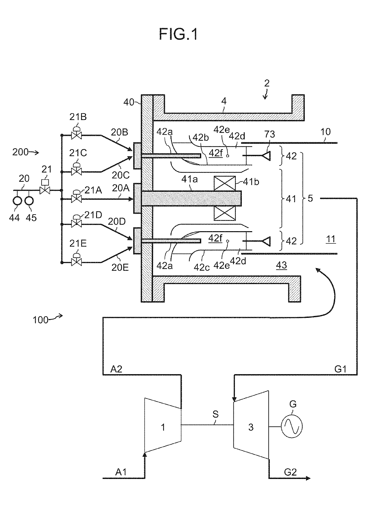
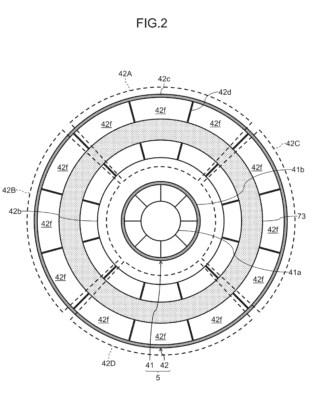
[0029]FIG. 1 is a schematic diagram representing an overall configuration of a gas turbine plant equipped with a gas turbine combustor according to a first embodiment of the present invention, and FIG. 2 depicts a configuration of a burner viewed from a combustion chamber side. A gas turbine plant 100 depicted in FIG. 1 includes a generator G and a gas turbine that is a prime mover which drives the generator G. The gas turbine includes a compressor 1, a gas turbine combustor (hereinafter, referred to as “combustor”) 2, and a turbine 3, and the compressor 1, the turbine 3, and the generator G are coupled to one another by a common shaft S.

[0030]The compressor 1 is driven by the turbine 3, and pressurizes air A1 taken in by suction via an air intake section (not depicted) to produce high-pressure air A2, and supplies the high-pressure air A2 to the combustor 2. The combustor 2 burns the high-pressure air A2 supplied from the compressor 1 and a fuel supplied from a f...

second embodiment

[0056]FIG. 9A is a characteristic diagram representing a relationship between a declining amount (correction amount) of a premixed fuel ratio and a gas turbine load and FIG. 9B is a characteristic diagram representing a relationship between a declining amount of a premixer fuel-air ratio and the gas turbine load under premixed fuel ratio control in a gas turbine combustor according to a second embodiment of the present invention.

[0057]The present embodiment is characterized in that the control device 50 is configured to increase controlled variables of the first to fifth gas control valves 21A to 21E under the premixed fuel ratio control to be associated with an increase in the gas turbine load. The flow rate of the premixed fuel is in a higher state as the gas turbine load is higher. Owing to this, for reducing the premixer fuel-air ratio to fall below the stable combustion limit (FIG. 9B), it is necessary to make lower the flow rate of the premixed fuel as the gas turbine load is ...

third embodiment

[0059]FIG. 10 is a characteristic diagram illustrating a burner metal temperature, a premixed fuel ratio, a fuel flow rate, and a power generation amount according to a third embodiment of the present invention, and corresponds to FIG. 7 according to the first invention. FIG. 11A is a characteristic diagram representing a relationship between a declining amount (correction amount) of a premixed fuel ratio and a gas turbine load and FIG. 11B is a characteristic diagram representing a relationship between a declining amount of a premixer fuel-air ratio and the gas turbine load under premixed fuel ratio control according to the present embodiment. FIGS. 11A and 11B correspond to FIGS. 9A and 9B according to the second embodiment.

[0060]In the present embodiment, a plurality of (two in the present embodiment) set values Ts1 and Ts2 (Ts12) are set for the detected temperature Tm as depicted in FIG. 10. In addition, different controlled variables of the first to fifth gas control valves 21...


PUM


Abstract

A flame produced within a premixer is promptly extinguished and a reduction in output power of a gas turbine associated with extinguishment is suppressed. In a gas turbine combustor including a diffusion burner and a premixed burner, the premixed burner is configured with a burner liner that surrounds the diffusion burner; a burner casing that surrounds the burner liner; a plurality of vanes that separate a cylindrical space between the burner liner and the burner casing into a plurality of premixers arranged side by side in a circumferential direction; a plurality of premixed fuel nozzles that inject a premixed fuel to the premixers; at least one thermometer installed to be buried in one of the vanes, and the like, and in a case in which a detection value of the thermometer exceeds a corresponding set value, an opening of each of premixed gas control valves is reduced and an opening of a diffusion gas control valve is increased in such a manner that a sum of flow rates of fuels supplied to the diffusion burner and the premixed burner remains unchanged.

Description

BACKGROUND OF THE INVENTION1. Field of the Invention[0001]The present invention relates to a gas turbine combustor, a gas turbine, and a control method for a gas turbine combustor.2. Description of the Related Art[0002]In recent years, further improvement in efficiency and reduction in nitrogen oxides (NOx) are required for a gas turbine equipped with a compressor, a combustor, a turbine, and the like to meet environmental conservation regulations and social demand. While there is known a method including increasing a temperature of a flame produced in a combustor to increase a temperature of combustion gas at an inlet of a gas turbine as a method of improving efficiency of the gas turbine, nitrogen oxides (NOx) emissions possibly increase to be associated with an increase in the temperature of the flame.[0003]On the other hand, as a combustor that suppresses nitrogen oxides (NOx) emissions, there is known a combustor that adopts premixed combustion (hereinafter, referred to as “pre...

Claims


Application Information

Patent Timeline
IPC IPC(8): F23R3/32F23R3/12F23R3/34
CPCF23R3/32F23R3/12F23R3/343F23R2900/03343F23R3/286F02C9/46F02C9/28F23R3/18F23R3/20F23R3/16F05D2240/35F23R3/14
Inventor ABE, KAZUKIHAYASHI, AKINORIWADA, YASUHIROTATSUMI, TETSUMAYOSHIDA, SHOHEI
Owner MITSUBISHI POWER LTD
Why Eureka
Try Eureka