Intraoral scanner, intraoral scanning system and method of controlling intraoral scanner

Active Publication Date: 2019-08-15
QISDA CORP
0 Cites 1 Cited by

AI-Extracted Technical Summary

Problems solved by technology

However, when the user places the intraoral scanner on a support frame or a table without pressing the stop button, the image sensor and the projection module are still operating continuously, such that power consumption and temperature increase.
At this time, the performance of the image sensor and the projection module m...

Method used

[0030]Furthermore, when the processor 18 determines that the sensing voltage of the magnetic sensor 20 is larger than or equal to the voltage threshold, the processor 18 may set three second variation thresholds corresponding to the three axes according to the three motion variations sensed by the motion sensor 14 and stores the three second variation thresholds in the memory unit 16, wherein the three second variation thresholds are smaller than the three first variation thresholds, respectively. When the processor 18 determines that the sensing voltage of the magnetic sensor 20 is smaller than the voltage threshold and all of the three motion variations are smaller than or equal to the three second variation thresholds, it means that the intraoral scanner 1 is removed from the support frame 3 and placed on a table or other planes. At this time, the intraoral scanner 1 should be still in a standby state rather than an idle state. Accordingly, the processor 18 may control the power supply 22 to stop supplying power to the image sensor 10 and the projection module 12, so as to reduce power consumption.
[0032]Moreover, the invention may further utilize the blur of an image sequence sensed by the image sensor 10 to determine whether the intraoral scanner 1 is in an idle state. In this embodiment, the memory unit 16 stores a blur threshold, wherein the blur threshold may be set according to practical applications. When the image sensor 10 senses an image sequence, the processor 18 determines whether a blur of at least one image of the image sequence is larger than or equal to the blur threshold. When the processor 18 determines that the blur of the at least one image is larger than or equal to the blur threshold, it means that the image sequence is not obtained by scanning a tooth, i.e. the intraoral scanner 1 is in an idle state. At this time, the processor 18 will disable at least one of the image sensor 10 and the projection module 12, such that at least one of the image sensor 10 and the projection module 12 stops operating, so as to reduce power consumption. When the processor 18 determines that the blur of the at least one image is smaller than the blur threshold, it means that the image sequence is obtained by scanning a tooth, i.e. the intraoral scanner 1 is in an operation state. At this time, the image sensor 10 and the projection module 12 can operate normally and continuously.
[0034]When the processor 18 determines that the current dist...

Benefits of technology

[0007]As mentioned in the above, the invention disposes a motion sensor in the intraoral scanner and the motion sensor senses three motion variations corresponding to three axes according to a motion state of the intraoral scanner. When at least one of the three motion variations is smaller than or equal to the three first variation thresholds, it means that the intraoral scanner is in an operation state, i.e. a user is using the intraoral scanner to scan a tooth. At this time, the image sensor and the projection module of the intraoral scanner will ...

Abstract

An intraoral scanner includes an image sensor, a projection module, a motion sensor, a memory unit and a processor. The motion sensor senses three motion variations corresponding to three axes according to a motion state of the intraoral scanner. The memory unit stores three first variation thresholds corresponding to the three axes. The processor determines whether the three motion variations are smaller than or equal to the three first variation thresholds, respectively. When the processor determines that at least one of the three motion variations is smaller than or equal to the three first variation thresholds, the processor enables the image sensor and the projection module. When the processor determines that all of the three motion variations are larger than the three first variation thresholds, the processor disables at least one of the image sensor and the projection module.

Application Domain

Impression capsSurgery +5

Technology Topic

Intraoral scannerImage sensor +3

Image

  • Intraoral scanner, intraoral scanning system and method of controlling intraoral scanner
  • Intraoral scanner, intraoral scanning system and method of controlling intraoral scanner
  • Intraoral scanner, intraoral scanning system and method of controlling intraoral scanner

Examples

  • Experimental program(1)

Example

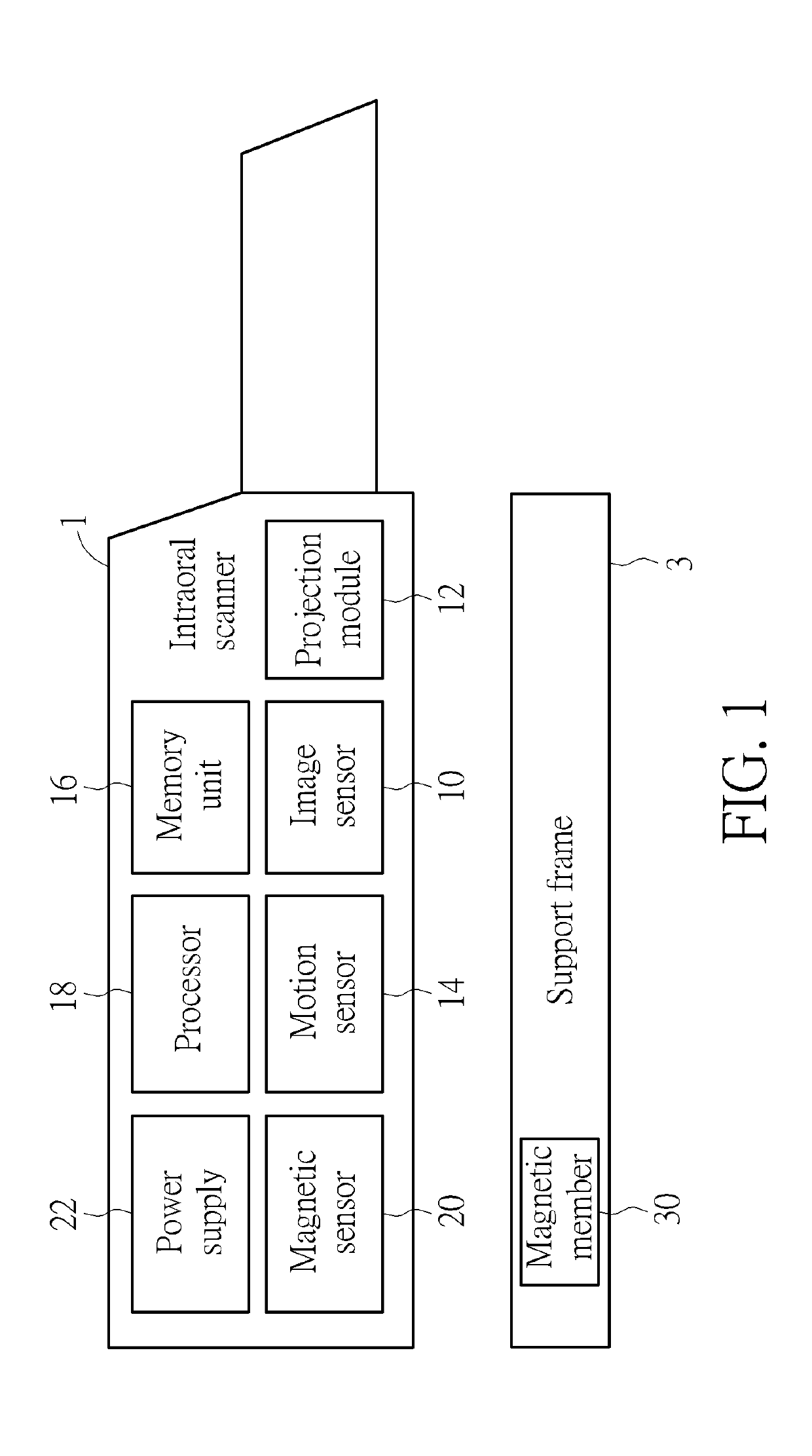
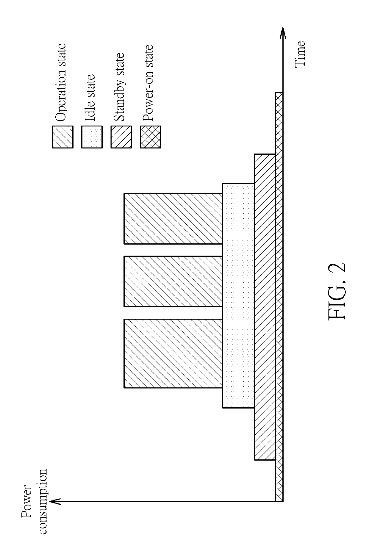
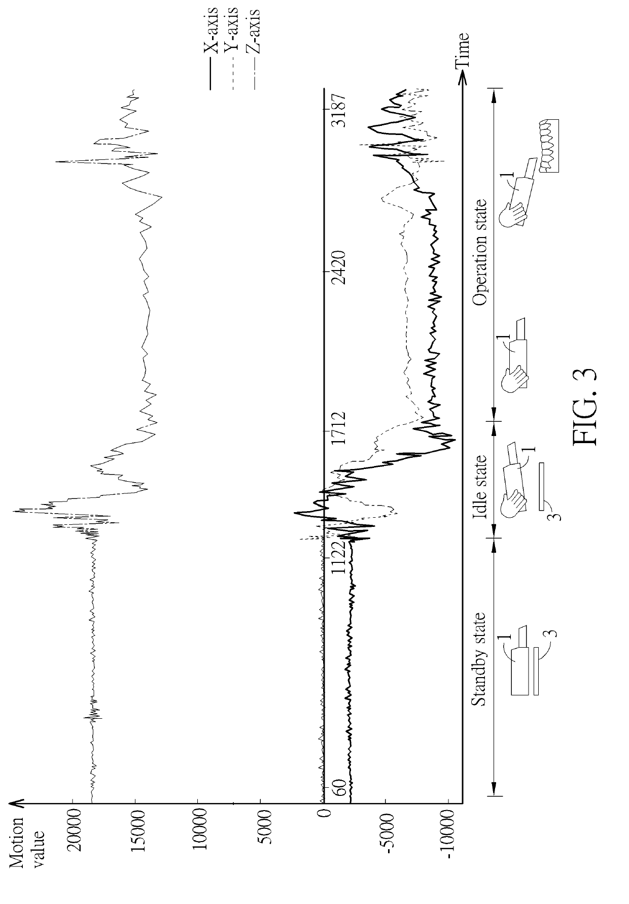
[0019]Referring to FIGS. 1 to 3, FIG. 1 is a functional block diagram illustrating an intraoral scanner 1 according to an embodiment of the invention, FIG. 2 is a schematic diagram illustrating power consumption of the intraoral scanner 1 in different states, and FIG. 3 is a curve diagram illustrating three-axis motion state of the intraoral scanner 1 sensed by the motion sensor 14.
[0020]As shown in FIG. 1, the intraoral scanner 1 comprises an image sensor 10, a projection module 12, a motion sensor 14, a memory unit 16, a processor 18, a magnetic sensor 20, and a power supply 22, wherein the processor 18 is electrically connected to the image sensor 10, the projection module 12, the motion sensor 14, the memory unit 16, the magnetic sensor 20, and the power supply 22. The power supply 22 is configured to supply power to the image sensor 10, the projection module 12, the motion sensor 14, the memory unit 16, the processor 18, the magnetic sensor 20, and other electronic components.
[0021]In practical applications, the projection module 12 may be a digital light processing (DLP) module or other projection modules to project a predetermined image to the three-dimensional object such as teeth, so as to form a constructed image on a surface of the three-dimensional object. The image sensor 10 may be an image capturing module, e.g., a charge-coupled device (CCD) sensor or a complementary metal-oxide semiconductor (CMOS) sensor, to capture the constructed image formed on the surface of the three-dimensional object such as teeth. The motion sensor 14 may be a G sensor, a gyro, or a combination thereof; the memory unit 16 may be a memory or other data storage devices; the processor 18 may be a processor or a controller with data calculating/processing function; the magnetic sensor 20 may a Hall sensor; and the power supply 22 may be a battery. In general, the intraoral scanner 1 may be further equipped with some necessary hardware or software components for specific purposes, such as a circuit board, applications, a communication module, etc., and it depends on practical applications.
[0022]In general, there is a power button (not shown) disposed on the intraoral scanner 1. When a user presses the power button, the processor 18 is woken up and the magnetic sensor 20 is enabled. At this time, the image sensor 10, the projection module 12, and the motion sensor 14 are disabled without power consumption. Accordingly, as shown in FIG. 2, when the intraoral scanner 1 is in a power-on state, the power consumption is very low.
[0023]Since the magnetic sensor 20 is enabled as the intraoral scanner 1 is powered on, the magnetic sensor 20 can operate normally. In this embodiment, the intraoral scanner 1 is adapted to be disposed on a support frame 3. The support frame 3 comprises a magnetic member 30 and the memory unit 16 stores a voltage threshold, wherein the voltage threshold may be set according to practical applications. The magnetic sensor 20 is configured to sense a magnetic flux of the magnetic member 30 to generate a sensing voltage. Then, the processor 18 determines whether the sensing voltage is larger than or equal to the voltage threshold. The invention may determine whether the intraoral scanner 1 is placed on the support frame 3 according to the comparison result of the sensing voltage and the voltage threshold.
[0024]When the processor determines that the sensing voltage is larger than or equal to the voltage threshold, it means that the intraoral scanner 1 is placed on the support frame 3, i.e. the intraoral scanner 1 is in a standby state. At this time, the processor 18 will enable the motion sensor 14, such that the motion sensor 14 can operate normally. Accordingly, as shown in FIG. 2, when the intraoral scanner 1 is in a standby state, the power consumption will increase slightly.
[0025]When the processor determines that the sensing voltage is smaller than the voltage threshold, it means that the intraoral scanner 1 is removed from the support frame 3, i.e. the intraoral scanner 1 is in an idle state. At this time, the processor 18 will control the power supply 22 to supply power to the image sensor 10 and the projection module 12. Accordingly, as shown in FIG. 2, when the intraoral scanner 1 is in an idle state, the power consumption will increase continuously.
[0026]Since the motion sensor 14 is enabled as the intraoral scanner 1 is in a standby state, the motion sensor 14 can operate normally. The motion sensor 14 is configured to sense three motion variations corresponding to three axes according to a motion state of the intraoral scanner 1, wherein the aforesaid three axes may be three axes X, Y, Z in a three-dimensional coordinate system and the motion sensor 14 may be a three-axis sensor. As shown in FIG. 3, the motion sensor 14 may sense three-axis motion state of the intraoral scanner 1 in different states, wherein the standby state represents that the intraoral scanner 1 is placed on the support frame 3, the idle state represents that the intraoral scanner 1 is removed from the support frame 3, and the operation state represents that the intraoral scanner 1 moves to an oral cavity and starts to scan a tooth. Furthermore, the memory unit 16 stores three first variation thresholds corresponding to the three axes, wherein the three first variation thresholds may be set according to practical applications.
[0027]The processor 18 determines whether the three motion variations of the intraoral scanner 1 are smaller than or equal to the three first variation thresholds, respectively, so as to determine that the intraoral scanner 1 is in an operation state or in an idle state. When the processor 18 determines that at least one of the three motion variations is smaller than or equal to the three first variation thresholds, it means that the intraoral scanner 1 is moving stably, i.e. the intraoral scanner 1 is in an operation state. At this time, the processor 18 will enable the image sensor 10 and the projection module 12, such that the image sensor 10 and the projection module 12 can operate normally. Accordingly, as shown in FIG. 2, when the intraoral scanner 1 is in an operation state, the power consumption is largest.
[0028]When the processor 18 determines that all of the three motion variations of the intraoral scanner 1 are larger than the three first variation thresholds, it means that the intraoral scanner 1 is shaking violently, i.e. the intraoral scanner 1 is in an idle state. At this time, the processor 18 will disable at least one of the image sensor 10 and the projection module 12, such that at least one of the image sensor 10 and the projection module 12 stops operating. Accordingly, as shown in FIG. 2, the power consumption of the intraoral scanner 1 in an idle state is smaller than the power consumption of the intraoral scanner 1 in an operation state.
[0029]The invention may take a difference between a maximum motion value and a minimum motion value sensed by the motion sensor 14 within a time period (three seconds, five seconds, etc.) to be the aforesaid motion variation. It is assumed that the first variation threshold corresponding to X-axis is equal to 100. If the difference between the maximum motion value and the minimum motion value corresponding to X-axis sensed by the motion sensor 14 within a time period is equal to 90, the motion variation corresponding to X-axis is smaller than the first variation threshold corresponding to X-axis. On the other hand, if the difference between the maximum motion value and the minimum motion value corresponding to X-axis sensed by the motion sensor 14 within a time period is equal to 120, the motion variation corresponding to X-axis is larger than the first variation threshold corresponding to X-axis. The determination for Y-axis and Z-axis is identical to the determination for X-axis, so it will not be depicted herein again.
[0030]Furthermore, when the processor 18 determines that the sensing voltage of the magnetic sensor 20 is larger than or equal to the voltage threshold, the processor 18 may set three second variation thresholds corresponding to the three axes according to the three motion variations sensed by the motion sensor 14 and stores the three second variation thresholds in the memory unit 16, wherein the three second variation thresholds are smaller than the three first variation thresholds, respectively. When the processor 18 determines that the sensing voltage of the magnetic sensor 20 is smaller than the voltage threshold and all of the three motion variations are smaller than or equal to the three second variation thresholds, it means that the intraoral scanner 1 is removed from the support frame 3 and placed on a table or other planes. At this time, the intraoral scanner 1 should be still in a standby state rather than an idle state. Accordingly, the processor 18 may control the power supply 22 to stop supplying power to the image sensor 10 and the projection module 12, so as to reduce power consumption.
[0031]The invention may set the aforesaid second variation threshold by adding a tolerance to the motion variation within a time period (three seconds, five seconds, etc.). It is assumed that the tolerance is equal to 10 and the motion variation corresponding to X-axis within a time period is equal to 20. Then, the second variation threshold corresponding to X-axis may be set to be 30. The setting of the second variation threshold for Y-axis and Z-axis is identical to the setting of the second variation threshold for X-axis, so it will not be depicted herein again. Still further, the second variation threshold may be set while the intraoral scanner 1 is powered on first time, but is not so limited.
[0032]Moreover, the invention may further utilize the blur of an image sequence sensed by the image sensor 10 to determine whether the intraoral scanner 1 is in an idle state. In this embodiment, the memory unit 16 stores a blur threshold, wherein the blur threshold may be set according to practical applications. When the image sensor 10 senses an image sequence, the processor 18 determines whether a blur of at least one image of the image sequence is larger than or equal to the blur threshold. When the processor 18 determines that the blur of the at least one image is larger than or equal to the blur threshold, it means that the image sequence is not obtained by scanning a tooth, i.e. the intraoral scanner 1 is in an idle state. At this time, the processor 18 will disable at least one of the image sensor 10 and the projection module 12, such that at least one of the image sensor 10 and the projection module 12 stops operating, so as to reduce power consumption. When the processor 18 determines that the blur of the at least one image is smaller than the blur threshold, it means that the image sequence is obtained by scanning a tooth, i.e. the intraoral scanner 1 is in an operation state. At this time, the image sensor 10 and the projection module 12 can operate normally and continuously.
[0033]Referring to FIGS. 4 and 5, FIG. 4 is a functional block diagram illustrating an intraoral scanner 1′ according to another embodiment of the invention and FIG. 5 is a schematic diagram illustrating the intraoral scanner 1′ and an object 5. The main difference between the intraoral scanner 1′ and the aforesaid intraoral scanner 1 is that the intraoral scanner 1′ further comprises a proximity sensor 24, wherein the processor 18 is electrically connected to the proximity sensor 24, as shown in FIG. 4. Furthermore, the memory unit 16 stores a distance threshold, wherein the distance threshold may be set according to practical applications. The proximity sensor 24 is configured to sense a current distance D between the intraoral scanner 1′ and an object 5 (e.g., a head of a patient), as shown in FIG. 5. Then, the processor 18 determines whether the current distance D is smaller than or equal to the distance threshold. The invention may determine that the intraoral scanner 1′ is in an operation state or in an idle state according to the comparison result of the current distance and the distance threshold.
[0034]When the processor 18 determines that the current distance D is smaller than or equal to the distance threshold, it means that the intraoral scanner 1′ moves to an oral cavity and starts to scan a tooth, i.e. the intraoral scanner 1′ is in an operation state. At this time, the processor 18 will enable the image sensor 10 and the projection module 12, such that the image sensor 10 and the projection module 12 can operate normally. On the other hand, when the processor 18 determines that the current distance D is larger than the distance threshold, it means that the intraoral scanner 1′ has moved away from the oral cavity, i.e. the intraoral scanner 1′ is in an idle state. At this time, the processor 18 will disable at least one of the image sensor 10 and the projection module 12, such that at least one of the image sensor 10 and the projection module 12 stops operating, so as to reduce power consumption.
[0035]Referring to FIG. 6, FIG. 6 is a functional block diagram illustrating an intraoral scanning system 7 according to another embodiment of the invention. As shown in FIG. 6, the intraoral scanning system 7 comprises a host device 70, the aforesaid intraoral scanner 1, and the aforesaid support frame 3. The intraoral scanner 1 may communicate with the host device 70 through wired or wireless connection. In practical applications, the host device 70 may be a computer.
[0036]In this embodiment, the host device 70 stores the aforesaid three first variation thresholds corresponding to the three axes. Accordingly, in the intraoral scanning system 7, the host device 70 may determine whether the three motion variations of the intraoral scanner 1 are smaller than or equal to the three first variation thresholds, respectively. When the host device 70 determines that at least one of the three motion variations is smaller than or equal to the three first variation thresholds, the host device 70 will control the processor 18 of the intraoral scanner 1 to enable the image sensor 10 and the projection module 12. On the other hand, when the host device 70 determines that all of the three motion variations are larger than the three first variation thresholds, the host device 70 will control the processor 18 of the intraoral scanner 1 to disable at least one of the image sensor 10 and the projection module 12. It should be noted that the detailed principle has been depicted in the above, so it will not be depicted herein again.
[0037]In this embodiment, the host device 70 may store the aforesaid voltage threshold. Accordingly, in the intraoral scanning system 7, the host device 70 may determine whether the sensing voltage of the magnetic sensor 20 is larger than or equal to the voltage threshold. When the host device 70 determines that the sensing voltage of the magnetic sensor 20 is larger than or equal to the voltage threshold, the host device 70 will control the processor 18 of the intraoral scanner 1 to enable the motion sensor 14. On the other hand, when the host device 70 determines that the sensing voltage of the magnetic sensor 20 is smaller than the voltage threshold, the host device 70 will control the processor 18 of the intraoral scanner 1 to control the power supply 22 to supply power to the image sensor 10 and the projection module 12. It should be noted that the detailed principle has been depicted in the above, so it will not be depicted herein again.
[0038]Furthermore, when the host device 70 determines that the sensing voltage of the magnetic sensor 20 is larger than or equal to the voltage threshold, the host device 70 may set the aforesaid three second variation thresholds corresponding to the three axes according to the three motion variations of the intraoral scanner 1 and stores the three second variation thresholds. When the host device 70 determines that the sensing voltage of the magnetic sensor 20 is smaller than the voltage threshold and all of the three motion variations of the intraoral scanner 1 are smaller than or equal to the three second variation thresholds, the host device 70 will control the processor 18 of the intraoral scanner 1 to control the power supply 22 to stop supplying power to the image sensor 10 and the projection module 12. It should be noted that the detailed principle has been depicted in the above, so it will not be depicted herein again.
[0039]In this embodiment, the host device 70 may store a blur threshold. Accordingly, in the intraoral scanning system 7, the host device 70 may determine whether a blur of at least one image of the image sequence is larger than or equal to the blur threshold. When the host device 70 determines that the blur of the at least one image is larger than or equal to the blur threshold, the host device 70 will control the processor 18 of the intraoral scanner 1 to disable at least one of the image sensor and the projection module. When the host device 70 determines that the blur of the at least one image is smaller than the blur threshold, the image sensor 10 and the projection module 12 can operate normally and continuously. It should be noted that the detailed principle has been depicted in the above, so it will not be depicted herein again.
[0040]In another embodiment, the intraoral scanner 1 of the intraoral scanning system 7 may be replaced by the intraoral scanner 1′ shown in FIG. 4. At this time, the host device 70 may store the aforesaid distance threshold. Accordingly, in the intraoral scanning system 7, the host device 70 may determine whether the aforesaid current distance D is smaller than or equal to the distance threshold. When the host device 70 determines that the current distance D is smaller than or equal to the distance threshold, the host device 70 will control the processor 18 of the intraoral scanner 1′ to enable the image sensor 10 and the projection module 12. On the other hand, when the host device 70 determines that the current distance D is larger than the distance threshold exceeding a predetermined time period, the host device 70 will control the processor 18 of the intraoral scanner 1′ to disable at least one of the image sensor 10 and the projection module 12. It should be noted that the detailed principle has been depicted in the above, so it will not be depicted herein again.
[0041]Referring to FIG. 7, FIG. 7 is a flowchart illustrating a method of controlling an intraoral scanner according to an embodiment of the invention. The method of controlling the intraoral scanner shown in FIG. 7 may be implemented by the aforesaid intraoral scanners 1, 1′ or intraoral scanning system 7. First, step S10 is performed to sense, by the motion sensor 14, three motion variations corresponding to three axes according to a motion state of the intraoral scanner 1, 1′. Then, step S12 is performed to determine whether the three motion variations are smaller than or equal to three first variation thresholds corresponding to the three axes, respectively. When determining that at least one of the three motion variations is smaller than or equal to the three first variation thresholds, step S14 is performed to enable the image sensor 10 and the projection module 12. When determining that all of the three motion variations are larger than the three first variation thresholds, step S16 is performed to disable at least one of the image sensor 10 and the projection module 12.
[0042]Referring to FIG. 8, FIG. 8 is a flowchart illustrating a method of controlling an intraoral scanner according to another embodiment of the invention. The method of controlling the intraoral scanner shown in FIG. 8 may be implemented by the aforesaid intraoral scanners 1, 1′ or intraoral scanning system 7. First, step S20 is performed to sense, by the magnetic sensor 20, a magnetic flux of the magnetic member 30 to generate a sensing voltage. Then, step S22 is performed to determine whether the sensing voltage is larger than or equal to the voltage threshold. When determining that the sensing voltage is larger than or equal to the voltage threshold, step S24 is performed to enable the motion sensor 14. When determining that the sensing voltage is smaller than the voltage threshold, step S26 is performed to control the power supply 22 to supply power to the image sensor 10 and the projection module 12. In this embodiment, when determining that the sensing voltage is larger than or equal to the voltage threshold, the method may set three second variation thresholds corresponding to the three axes according to the three motion variations, wherein the three second variation thresholds are smaller than the three first variation thresholds, respectively. When determining that the sensing voltage is smaller than the voltage threshold and all of the three motion variations are smaller than or equal to the three second variation thresholds, the method may control the power supply 22 to stop supplying power to the image sensor 10 and the projection module 12.
[0043]Referring to FIG. 9, FIG. 9 is a flowchart illustrating a method of controlling an intraoral scanner according to another embodiment of the invention. The method of controlling the intraoral scanner shown in FIG. 9 may be implemented by the aforesaid intraoral scanner 1′ or intraoral scanning system 7. First, step S30 is performed to sense, by the proximity sensor 24, a current distance D between the intraoral scanner 1′ and an object 5. Then, step S32 is performed to determine whether the current distance D is smaller than or equal to a distance threshold. When determining that the current distance D is smaller than or equal to the distance threshold, step S34 is performed to enable the image sensor 10 and the projection module 12. When determining that the current distance D is larger than the distance threshold exceeding a predetermined time period, step S36 is performed to disable at least one of the image sensor 10 and the projection module 12.
[0044]Referring to FIG. 10, FIG. 10 is a flowchart illustrating a method of controlling an intraoral scanner according to another embodiment of the invention. The method of controlling the intraoral scanner shown in FIG. 10 may be implemented by the aforesaid intraoral scanners 1, 1′ or intraoral scanning system 7. First, step S40 is performed to sense, by the image sensor 10, an image sequence. Then, step S42 is performed to determine whether a blur of at least one image of the image sequence is larger than or equal to a blur threshold. When determining that the blur of the at least one image is larger than or equal to the blur threshold, step S44 is performed to disable at least one of the image sensor 10 and the projection module 12. When determining that the blur of the at least one image is smaller than the blur threshold, step S46 is performed to enable the image sensor 10 and the projection module 12 to operate normally and continuously.
[0045]It should be noted that the detailed embodiments of the method of controlling the intraoral scanner of the invention are mentioned in the above and those will not be depicted herein again. Furthermore, each part or function of the control logic of the method of controlling the intraoral scanner shown in FIGS. 7 to 10 may be implemented by software, hardware or the combination thereof.
[0046]As mentioned in the above, the invention disposes a motion sensor in the intraoral scanner and the motion sensor senses three motion variations corresponding to three axes according to a motion state of the intraoral scanner. When at least one of the three motion variations is smaller than or equal to the three first variation thresholds, it means that the intraoral scanner is in an operation state, i.e. a user is using the intraoral scanner to scan a tooth. At this time, the image sensor and the projection module of the intraoral scanner will be enabled, such that the image sensor and the projection module can operate normally. When all of the three motion variations are larger than the three first variation thresholds, it means that the intraoral scanner is in an idle state. At this time, at least one of the image sensor and the projection module will be disabled, such that at least one of the image sensor and the projection module stop operating. Accordingly, the invention can reduce power consumption and avoid temperature rise effectively while the intraoral scanner is in an idle state. Furthermore, the invention may utilize the proximity sensor or the blur of image to assist in determining that the intraoral scanner is in an operation state or in an idle state. Moreover, the invention may utilize the magnetic sensor to determine whether the intraoral scanner is placed on the support frame, so as to further determine that the intraoral scanner is in a standby state or in an idle state for switching related component correspondingly, such that the power consumption can be further reduced.
[0047]Those skilled in the art will readily observe that numerous modifications and alterations of the device and method may be made while retaining the teachings of the invention. Accordingly, the above disclosure should be construed as limited only by the metes and bounds of the appended claims.

PUM

no PUM

Description & Claims & Application Information

We can also present the details of the Description, Claims and Application information to help users get a comprehensive understanding of the technical details of the patent, such as background art, summary of invention, brief description of drawings, description of embodiments, and other original content. On the other hand, users can also determine the specific scope of protection of the technology through the list of claims; as well as understand the changes in the life cycle of the technology with the presentation of the patent timeline. Login to view more.

Similar technology patents

Semiconductor device including capacitorless ram

ActiveUS20090310431A1reduce power consumptionretention time be lengthen
Owner:LONGITUDE LICENSING LTD

Efficient route update protocol for wireless sensor network

InactiveUS20050157698A1minimize power consumption differencereduce power consumption
Owner:SAMSUNG ELECTRONICS CO LTD +1

Lighted bollard

InactiveUS20060109667A1reduce power consumption
Owner:LEADER MFG

Classification and recommendation of technical efficacy words

  • reduce power consumption
  • normal operation

Electrode array for use in medical stimulation and methods thereof

InactiveUS20050038489A1reduce power consumptionincrease battery life
Owner:CASE WESTERN RESERVE UNIV

Method of reselecting a cell based on priorities

ActiveUS20090181676A1ensure quality of servicereduce power consumption
Owner:LG ELECTRONICS INC

Organic light-emitting devices with mixed electron transport materials

InactiveUS20060204784A1good luminance efficiency and stabilityreduce power consumption
Owner:EASTMAN KODAK CO

Gas-liquid separator for fuel cell system

InactiveUS20090162730A1normal operation
Owner:TOYOTA BOSHOKU KK

Data collector control system with automatic communication port switch

InactiveUS20070213862A1normal operation
Owner:PROMOS TECH INC

Image forming device, installing method, and recording medium

InactiveUS20110061048A1normal operation
Owner:RICOH KK

Wireless power receiving terminal and wireless charging system

ActiveUS20180358844A1large operate voltage rangenormal operation
Owner:NINGBO WEIE ELECTRONICS TECH CO LTD

DLL circuit

InactiveUS6940325B2normal operation
Owner:SK HYNIX INC
Why Eureka
Try Eureka