

Robot, Printer, And Optical Signal Transmitter
a technology of optical signal transmitter and printer, which is applied in the direction of mechanical equipment, manufacturing tools, instruments, etc., can solve the problem of difficulty in reducing heigh
- Summary
- Abstract
- Description
- Claims
- Application Information
AI Technical Summary
Benefits of technology
Problems solved by technology
Method used
Image

Examples
first embodiment
[0024]First, a robot according to the first embodiment of the invention is explained.
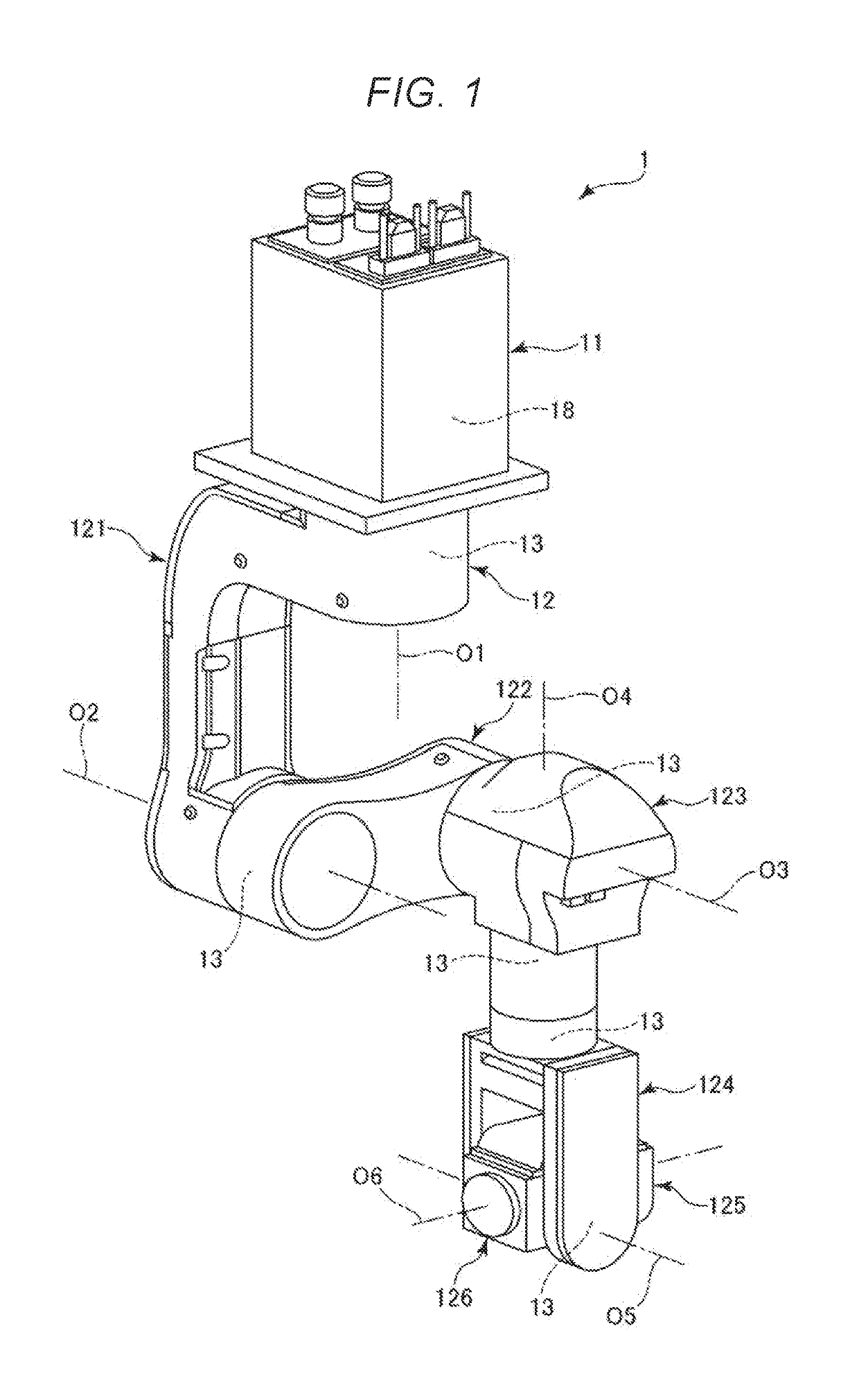
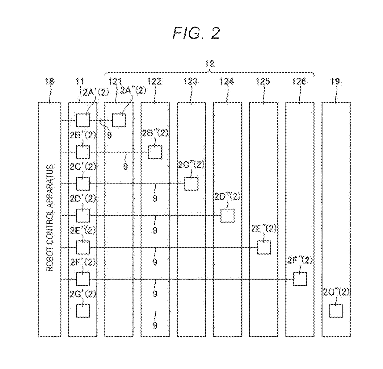
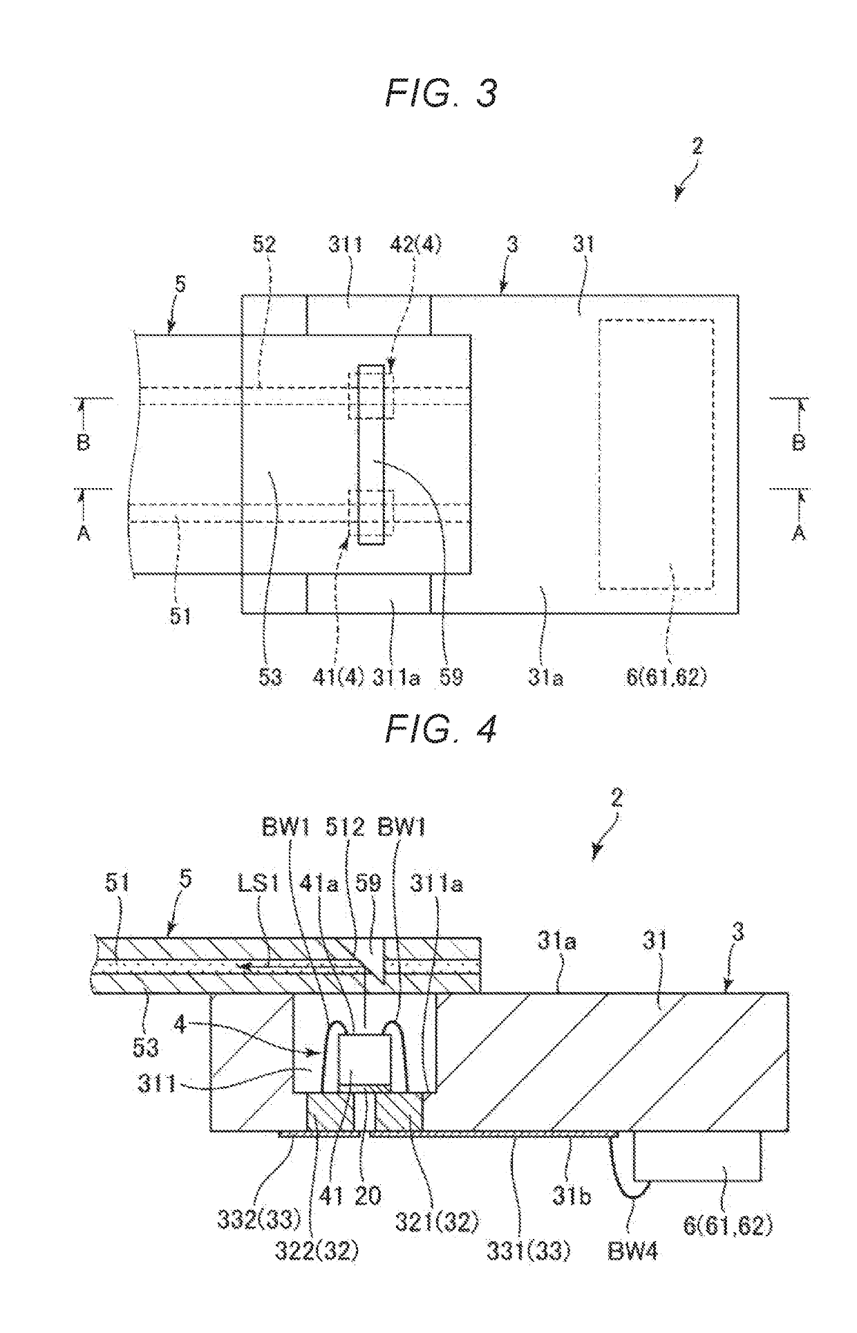
[0025]FIG. 1 is a perspective view showing a robot according to the first embodiment of the invention. FIG. 2 shows an arrangement of optical signal transmitters of the robot shown in FIG. 1. FIG. 3 is a top view showing the optical signal transmitter. FIG. 4 is a sectional view along line A-A in FIG. 3. FIG. 5 is a sectional view along line B-B in FIG. 3. FIG. 6 is a bottom view showing the optical signal transmitter. FIG. 7 is a top view showing the optical signal transmitter without illustration of a light guide part. Hereinafter, for convenience of explanation, the near side of the paper in FIG. 3 is also referred to as “upper” and the far side of the paper is also referred to as “lower”.
[0026]A robot 1 shown in FIG. 1 may perform work of e.g. feeding, removing, carrying, assembly, etc. of precision apparatuses and components forming the apparatuses. Note that the usage of the robot 1 is not lim...
second embodiment
[0069]Next, an optical signal transmitter according to the second embodiment of the invention will be explained.
[0070]FIG. 8 is a top view showing the optical signal transmitter according to the second embodiment of the invention. FIG. 9 is a sectional view along line C-C in FIG. 8. FIG. 10 is a sectional view along line D-D in FIG. 8. FIG. 11 is a top view showing a modified example of the optical signal transmitter shown in FIG. 8.
[0071]The embodiment is the same as the above described first embodiment except that the configuration of the optical signal transmitter is different. Note that, in the following description, the embodiment will be explained with a focus on the differences from the above described first embodiment and the explanation of the same items will be omitted. In FIGS. 8 to 11, the same configurations as those of the above described embodiment have the same signs.
[0072]As shown in FIGS. 8 to 10, in the optical signal transmitter 2 of the embodiment, the concave p...
third embodiment
[0074]Next, an optical signal transmitter according to the third embodiment of the invention will be explained.
[0075]FIG. 12 is a top view showing the optical signal transmitter according to the third embodiment of the invention. FIG. 13 is a bottom view showing the optical signal transmitter shown in FIG. 12.
[0076]The embodiment is the same as the above described first embodiment except that the configuration of the optical signal transmitter is different. Note that, in the following description, the embodiment will be explained with a focus on the differences from the above described first embodiment and the explanation of the same items will be omitted. In FIGS. 12 and 13, the same configurations as those of the above described embodiments have the same signs.
[0077]As shown in FIG. 12, in the optical signal transmitter 2 of the embodiment, the circuit element 6 is placed on the bottom surface 311a of the concave portion 311. Further, the circuit element 6 is placed between the li...
PUM
 Abstract
Description
Claims
Application Information