Illuminated medical devices

a medical device and illumination technology, applied in the field of medical devices, can solve the problems of not providing sufficient illumination for medical devices, most medical devices with integrated light sources often fail to direct or concentrate illumination to the desired surgical field, and achieve the effects of improving thermal dissipation, simple assembly mechanism, and maximizing illumination and visibility

Active Publication Date: 2019-08-22
OBP SURGICAL CORP
View PDF5 Cites 12 Cited by
  • Summary
  • Abstract
  • Description
  • Claims
  • Application Information

AI Technical Summary

Benefits of technology

[0005]It is an object of the present invention to provide a medical device with an illumination assembly having a plurality of light sources in which each light source is particularly configured and positioned to maximize illumination and visibility to desired surgical fields. In certain embodiments, each light source is configured and positioned to provide illumination only to the desired surgical field(s) while not providing or limiting illumination outside of the desired surgical fields. It is another object of the present invention to provide a medical device with an illumination assembly using a flexible circuit board to particularly configure and position light sources for illuminating surgical fields. It is yet another object of the present invention to provide a medical device that uses a specially designed flexible circuit board that improves thermal dissipation. It is a further object of the present invention to provide a medical device with a simple assembly mechanism that can quickly change from an open circuit configuration to a closed circuitry prior to actual use of the medical device. It is still a further object of the present invention provide a medical device with a mechanism to easily separate batteries from the rest of the medical device prior to disposal. Finally, it is also an object of the present invention to provide a medical device that achieves any one of the above noted objects while having an ergonomic design that gives rise to a more secure grip and an easier control for operating the medical device.

Problems solved by technology

Illuminating body cavities using a medical device is a well-documented problem in the medical field.
In one aspect, existing medical devices fail to provide sufficient illumination.
That is, most medical devices with integrated light sources often fail to direct or concentrate illumination to a desired surgical field.
In other cases, existing medical devices illuminate an overly large area and create a glare that interferes with a physician's field of view.
However, when a single use illuminated medical device with a battery power source is disposed with the battery still intact, incineration of heavy metals contained in the battery may release toxic gases into the atmosphere causing environmental issues.
Moreover, most illuminated medical devices often require a short assembly of parts prior to their use.
This often creates a problem in an urgent environment where surgeons and / or other medical professionals cannot afford to waste precious time in assembling a new device prior to its use.
Shipping illuminated medical devices pre-assembled is usually not a viable solution because such method may violate various regulations for manufacturing and shipping medical devices, particularly devices that use batteries or other power sources.

Method used


Image

  • Illuminated medical devices
  • Illuminated medical devices
  • Illuminated medical devices

Examples


first embodiment

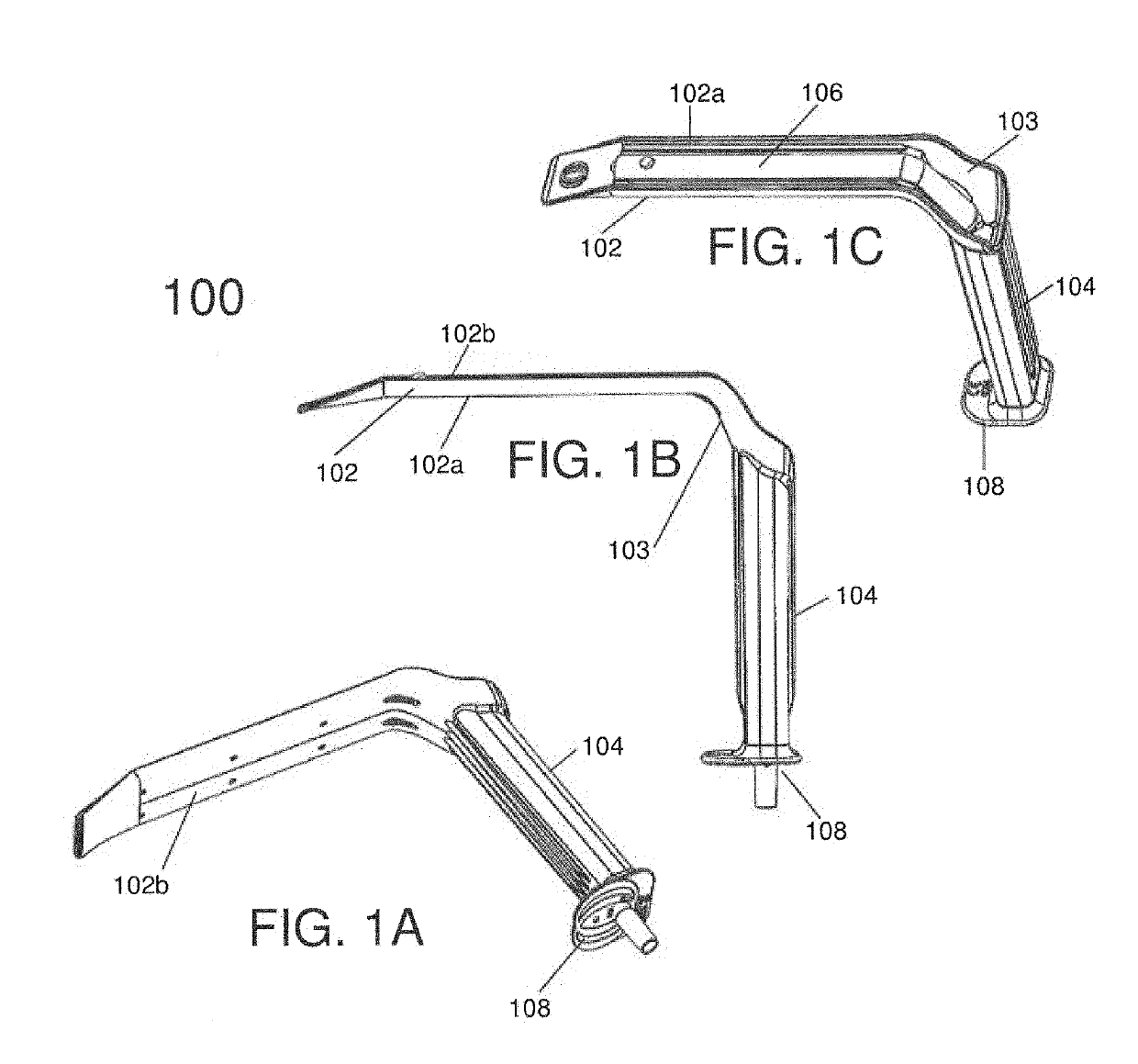
[0053]Referring to the drawings, FIGS. 1A-1C thereof show different views of a retractor 100 in accordance with the present invention. As shown in these figures, the retractor 100 includes a blade portion 102 having a first (bottom) surface 102a and an opposing second (bottom) surface 102b and a proximal end and a distal end. The proximal end is defined herein as the end of the blade portion closer to a handle of the retractor and the distal end is defined as the tip end of the blade portion opposing the proximal end. The retractor 100 further includes a handle portion 104 that extends from the blade portion 102 at an angle. In this illustrative embodiment, the handle portion 104 is generally perpendicularly joined to the blade portion at the proximal end of the blade portion. In some versions, the angle may vary, for example, at 95°, 100°, 105°, etc., without limiting the scope of the present embodiment. The portion of the retractor 100 where the blade portion 102 and the handle po...

second embodiment

[0087]Notably, the retractor 900 of the second embodiment includes a textured gripping surface 902 formed on the second surface 102b of the blade tip 102c. The textured gripping surface 902 may also be referred herein as a textured non-slip pattern 902. The textured gripping surface 902 provides a non-slip surface to prevent slippage of the retractor against patient's tissue. In one version, the textured gripping surface 902 is formed only on the second surface 902b of the blade. In another version, the textured gripping surface 902 is formed on either or both of the first and second surfaces of the blade. In yet other versions, the textured gripping surface 902 is not limited to the tip of the blade, but may be provided over a portion of the blade's first and / or second surfaces or over the whole first and / or second surface of the blade.

[0088]As shown in FIGS. 9A-9C, the textured gripping surface 902 comprises a plurality of elongated ridges formed on at least a portion of the secon...

fourth embodiment

[0128]FIGS. 16A-D and FIG. 17B show a surgical retractor 1600, 1700 that uses the LED flex circuit 1500b of FIGS. 15B-C. FIGS. 16A-D show the LED circuit 1500b assembly with a retractor blade cover 1606. FIG. 16A is an exploded view of the LED flex circuit 1500b and the retractor blade cover 1606, while FIG. 16B shows the positioning of the LED flex circuit 1500b relative to the blade cover 1606. As shown in these figures, the particular shape, size, and contour of the LED flex circuit 1500b is designed to correspond to a specific position on the retractor blade cover 1606 and to the openings formed in the retractor blade cover 1606. Specifically, the size and positioning of the LEDs and the wings 1604 or tabs and the thickness of the LED flex circuit are designed to smoothly fit with the retractor blade and the retractor blade cover 1606 so as not to impede with other functionalities of the retractor.

[0129]As shown in FIG. 16A, the LEDs 1602 are mounted on portions of the LED circu...


PUM


Abstract

A surgical retractor comprising a handle and a blade extending at an angle from the handle; an illumination assembly having a plurality of direct light sources provided on the blade, at least one of the light sources being angled differently relative to the blade than another one of the light sources; and a cover configured to enclose the illumination assembly, wherein the cover comprises a plurality of openings, each opening corresponding in position to a respective light source of the illumination assembly when the cover is attached to the blade.

Description

FIELD OF INVENTION[0001]The present invention relates to medical devices and, more particularly, to illuminated medical devices having light sources to illuminate surgical fields.BACKGROUND[0002]Illuminating body cavities using a medical device is a well-documented problem in the medical field. In one aspect, existing medical devices fail to provide sufficient illumination. That is, most medical devices with integrated light sources often fail to direct or concentrate illumination to a desired surgical field. In other cases, existing medical devices illuminate an overly large area and create a glare that interferes with a physician's field of view. In another aspect, current lighting technology creates heat as a by-product. Even high efficiency LEDs only convert 30-40% of their energy into light and the rest is converted into heat energy. This heat energy has the potential to burn patients and to damage tissue, and thus, must be avoided. Accordingly, there is a need for a solution t...

Claims


Application Information

Patent Timeline
Patent Type & Authority Applications(United States)
IPC IPC(8): A61B90/30A61B1/32A61B17/02
CPCA61B90/30A61B1/32A61B17/02A61B2090/061A61B2218/008A61B2090/309A61B2017/00734A61B2017/00858A61B2090/306A61B1/267A61B1/303A61B1/0684A61B1/0676A61B1/0623A61B1/00075A61B1/00108A61B1/0011A61B1/00032H05K2201/10106H05K1/0209H05K1/189A61B1/0625
Inventor SWIFT, JEFFREY RALPHSWIFT, JASONTRAUB, MATTHEWLAUDER, NICHOLAS
Owner OBP SURGICAL CORP
Why Eureka
Try Eureka