Intravascular delivery system and method for percutaneous coronary intervention

a delivery system and intravascular technology, applied in the field of medical devices, can solve the problems of compromising affecting the smooth advancement of the revascularization device, and reducing the flexibility of the balloon, so as to achieve the effect of minimal trauma and efficient delivery

Pending Publication Date: 2019-08-22
VANTIS VASCULAR INC
View PDF6 Cites 27 Cited by
  • Summary
  • Abstract
  • Description
  • Claims
  • Application Information

AI Technical Summary

Benefits of technology

[0036]It is therefore an object of the present invention to provide a medical device for intravascular applications that attains delivery of an interventional device (such as a balloon, or a stent) in an efficient and minimally traumatic fashion, to, and beyond, a coronary artery obstructive lesion by virtue of an integrated distal micro-catheter system.
[0037]It is another object of the present invention to provide an intravascular delivery system using a coaxial, highly flexible delivery micro-catheter (which has a diameter at its distal tip not exceeding 1.0 mm), which is specifically configured to track over a 0.009-0.014″ guidewire, and which carries a pre-dilatation balloon attached in close proximity thereto, to, and beyond, the target area, to attain a “crossability” of the pre-dilatation balloon (or other interventional device) that is superior to that of conventional balloon angioplasty catheters.

Problems solved by technology

The advancement of the revascularization devices, such as balloons or stent delivery systems, within the blood vessels to a treatment site can be challenging in case of tortuosity and / or calcification of the vessels.
The compressed stent mounted on a balloon significantly reduces the flexibility of the balloon and compromises its smooth advancement through the coronary artery.
This can make the stent difficult or impossible to reach a treatment site and risks dislodgement of the un-deployed stent off of its delivery balloon.
The use of guide catheters alone to “back up” the advancement of the revascularization devices to the coronary arteries may be limited and challenging.
However, despite the additional support, the lesion to be treated can still be difficult or nearly impossible to pass through with a pre-dilatation balloon catheter, or a stent delivery system, due to fibrosis, calcification, and / or angulation at the lesion site.
One of the limitations of the currently used guide extension devices is that they use a relatively blunt and large caliber cylindrical distal end.
Relatively high profile distal edges have a limited deliverability of the guide extension in many cases, and permit the advancement only to the proximal or mid portion of the coronary artery to be treated.
The Gill device, however, does not envision an inner catheter to permit easy and atraumatic crossing of the lesion to be treated.
Although a concept of a tapered piece inside a guide extension catheter is envisioned by Root, the prior art system uses a very short taper, and does not envision the taper as an elongated integrated member of the whole system, nor does it envision that a pre-dilatation balloon can be attached to the tapered delivery micro-catheter to be delivered to the target treatment area.
In addition, the prior art fails to envision a substantially “flush” interface between the inner catheter and the outer guide extension inside the vessel, or that the inner and outer catheter members would be reversibly fit or locked together to allow the entire system to be moved easily as one integral device.

Method used


Image

  • Intravascular delivery system and method for percutaneous coronary intervention
  • Intravascular delivery system and method for percutaneous coronary intervention
  • Intravascular delivery system and method for percutaneous coronary intervention

Examples


Embodiment Construction

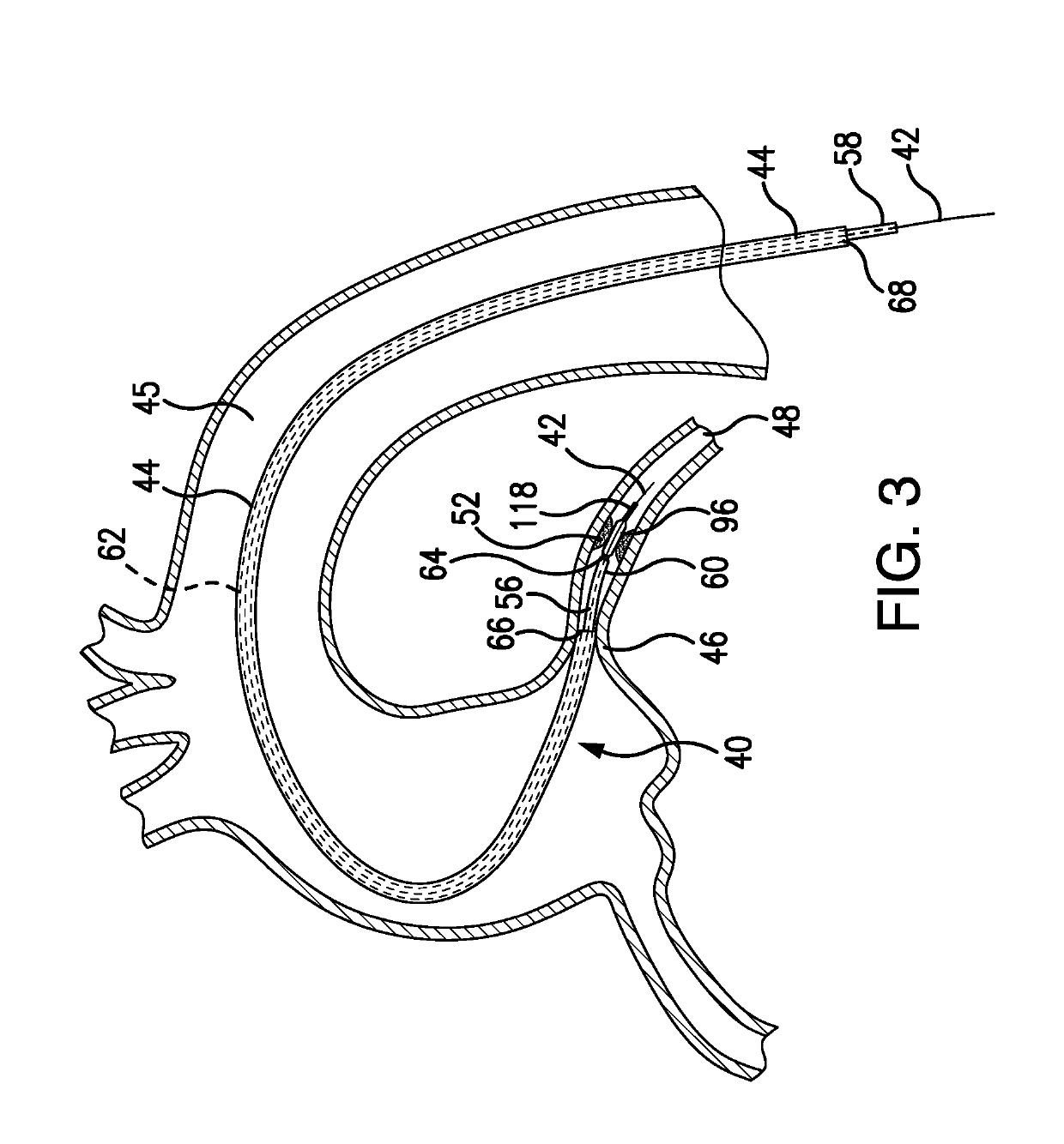
[0122]Depicted in FIGS. 3-23F, is the subject intravascular delivery system 40 and method for percutaneous coronary intervention. The subject system 40 includes a guide catheter extension sub-system (outer member) and an interventional device delivery sub-system (inner member) cooperating under control of a surgeon during a cardiac procedure. Although the interventional device delivery sub-system may be used for delivery of various cardiac interventional devices, in one of implementations, as an example only, but not to limit the scope of the subject invention to this particular embodiment, the subject interventional device delivery sub-system will be further described as adapted for delivery of a balloon member for performing the pre-dilatation procedure.

[0123]Therefore, in the exemplary embodiment described herein, the subject system 40 is referred to herein as a guide catheter extension / pre-dilatation system which is used for cardiac procedures in conjunction with a guide wire 42...


PUM


Abstract

The subject guide catheter extension / pre-dilatation system includes an outer delivery sheath, an inner member extending within the sheath, and a mechanism for engagement / disengagement of the inner member to / from the sheath. The inner member is configured with a tapered distal tip having a delivery micro-catheter and a pre-dilatation balloon member attached to the tapered distal tip. The guidewire and a guide catheter are advanced to the vicinity of the treatment site within a blood vessel. Subsequently, the inner member and outer delivery sheath, in their engaged configuration, are advanced along the guidewire inside the guide catheter towards the site of treatment. At the treatment site, the balloon member is inflated for pre-dilatation treatment. The inner member is disengaged and retracted from the outer delivery sheath, and a stent is delivered to the treatment site.

Description

REFERENCE TO RELATED APPLICATIONS[0001]The present Utility patent application is a Continuation-in-Part (CIP) of the Utility patent application Ser. No. 15 / 899,603, filed on 20 Feb. 2018, currently pending.INCORPORATION BY REFERENCE[0002]U.S. patent application Ser. No. 15 / 899,603, currently pending, is hereby incorporated by reference.FIELD OF THE INVENTION[0003]The present invention is directed to medical devices, and, in particular, to minimally invasive devices used for treatment within the human vasculature, such as, for example, coronary arteries.[0004]More in particular, the present invention addresses a delivery system for percutaneous coronary intervention adapted specifically for intravascular balloon angioplasty, and enhanced by pre-dilatation guide catheter extension capabilities.[0005]The present invention is also directed to medical devices designed for atraumatic, convenient and fast delivery of various interventional devices, such as, for example, a pre-dilatation ba...

Claims


Application Information

Patent Timeline
Patent Type & Authority Applications(United States)
IPC IPC(8): A61M25/10A61F2/958A61F2/966A61M25/00
CPCA61M25/104A61F2/958A61F2/966A61M25/0012A61M2205/0266A61M2025/1079A61F2240/001A61M2025/1081
Inventor FISCHELL, TIM A.SALTIEL, FRANK S.
Owner VANTIS VASCULAR INC
Why Eureka
Try Eureka