Guide catheter extension system with a delivery micro-catheter configured to facilitate percutaneous coronary intervention

Active Publication Date: 2019-08-22
VANTIS VASCULAR INC
View PDF9 Cites 19 Cited by
  • Summary
  • Abstract
  • Description
  • Claims
  • Application Information

AI Technical Summary

Benefits of technology

[0039]Preferably, the micro-catheter is formed of a flexible material having differential flexibility along its length. The flexibility of the micro-catheter increases towards its distal end. In one embodiment, the micro-catheter is configured with a flat wire helical coil extending along the predetermined length of the micro-cathe

Problems solved by technology

The advancement of the revascularization devices, such as balloons or stent delivery systems, within the blood vessels to a treatment site can be challenging in case of tortuosity and/or calcification of the vessels.
The use of guide catheters alone to “back up” the advancement of the revascularization devices to the coronary arteries may be limited and challenging.
However, despite the additional support, the lesion to be treated can still be difficult or nearly impossible to pass through with a stent delivery system, due to fibrosis, calcification, and/or angulation at the lesion site.
One of the limitations of the currently used guide extension devices is that they use a relat

Method used


Image

  • Guide catheter extension system with a delivery micro-catheter configured to facilitate percutaneous coronary intervention
  • Guide catheter extension system with a delivery micro-catheter configured to facilitate percutaneous coronary intervention
  • Guide catheter extension system with a delivery micro-catheter configured to facilitate percutaneous coronary intervention

Examples


Embodiment Construction

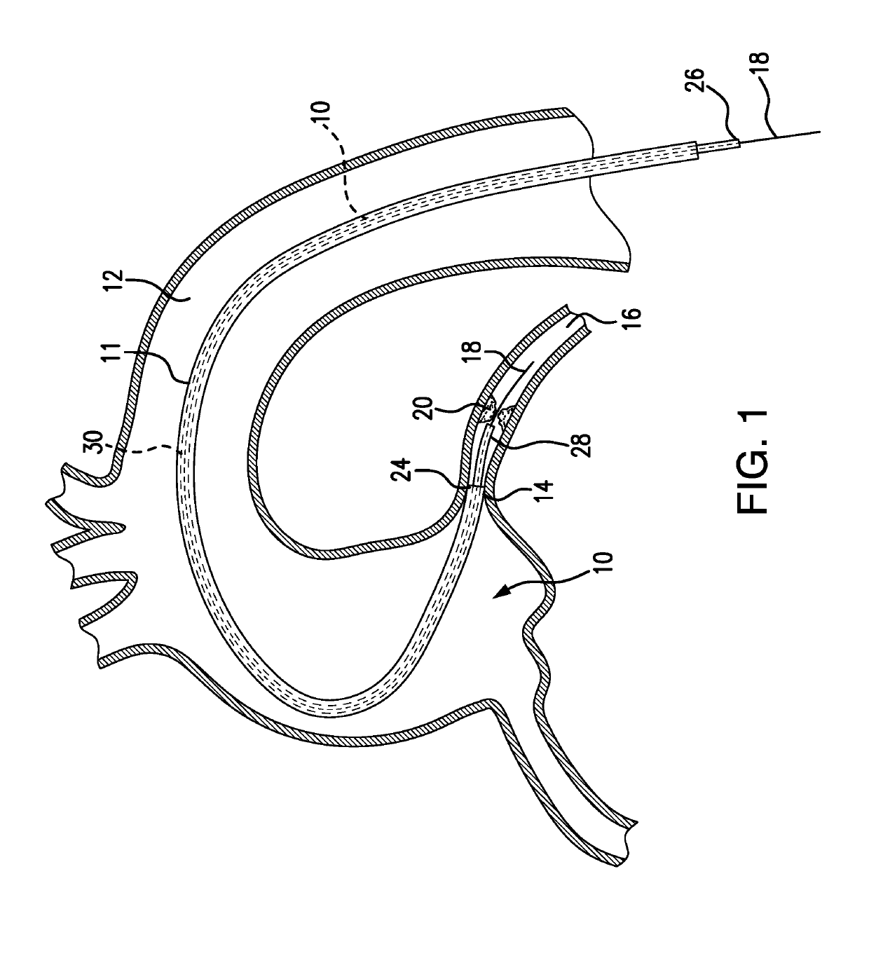
[0092]FIG. 1 depicts a subject guide catheter extension system 10 which is used in conjunction with a guide catheter 11. At the initial stage of the procedure, the guide catheter 11 is advanced through a blood vessel 12 (such as the aorta) to a position adjacent to the ostium 14 of the coronary artery 16. A guidewire 18 is used during the cardiac procedure to guide the guide extension system 10 within the artery 16 toward a target location 20, as will be detailed in following paragraphs.

[0093]Subsequent to positioning of the distal end of the guide extension system 10 at the target location 20, a treatment system, such as a balloon catheter or stent system, may be advanced through the guide extension system 10 into the coronary artery 16 to the target location 20 to perform an intended cardiac treatment.

[0094]In order to reliably reach the target location, and even pass beyond the target location 20, the subject guide extension system 10 extends through the guide catheter 11 and bey...


PUM


Abstract

The subject guide catheter extension system with a micro-catheter delivery catheter includes an outer sheath, an inner member extending within the sheath, and a mechanism for engagement/disengagement of the inner member to/from the sheath. Several mechanisms of engagement/disengagement between the inner and outer members are provided including a friction mechanism, threaded mechanism, pull away sheath, and engagement/disengagement mechanism for pusher's handles. The sheath and the inner member are modified for different engagement/disengagement mechanisms operation. A micro-catheter delivery system provides for an improved atraumatic crossability to the treatment site in an expedited and simplified fashion. During a procedure, a guidewire along with a guide catheter are advanced to the vicinity of the treatment site within a blood vessel. Subsequent thereto, the subject guide catheter extension system is manipulated to advance the micro-catheter along the guidewire inside the guide catheter towards and beyond the site of interest. Once the micro-catheter is in place, the outer sheath slides along the micro-catheter until reaching the lesion, and then the inner member is removed from the sheath, and the sheath then is ready for passing the treatment catheter (stent/balloon) towards the lesion to be treated.

Description

FIELD OF THE INVENTION[0001]The present invention is directed to medical devices, and particularly, to minimally invasive devices used for treatments within the human vasculature, such as, for example, coronary arteries.[0002]The present invention is further directed to devices designed for atraumatic, fast, simple delivery and replacement of catheters in coronary arteries or other blood vessels in the human body to facilitate percutaneous revascularization.[0003]The present invention is also directed to medical devices for intravascular procedures using a guide catheter extension system equipped with a delivery micro-catheter that permits easy delivery of the distal portion of the tubular guide extension system to, and beyond, a lesion to be stented (treated).[0004]The present invention further is directed to a medical device that includes a thin-walled tubular guide catheter extension system that is delivered co-axially to, and / or beyond, a coronary artery obstruction lesion by vi...

Claims


Application Information

Patent Timeline
IPC IPC(8): A61M25/09A61M25/10A61M25/01
CPCA61M25/0905A61M25/104A61M25/0169A61M25/09041A61M25/0102A61M25/0068A61M2025/0183A61M2025/0042A61M25/0054A61M2025/0004A61M25/0097A61M25/0662A61M2025/0681A61M25/0052A61M2025/0006A61M25/0668
Inventor FISCHELL, TIM A.SALTIEL, FRANK S.
Owner VANTIS VASCULAR INC
Why Eureka
Try Eureka