Diffuser assembly for diffusing a liquid in irrigation plants, and irrigation plant comprising a plurality of diffuser assemblies

a technology of diffuser assembly and diffuser, which is applied in the direction of movable spraying apparatus, pipe-joints, adjustable joints, etc., can solve the problems of diffusers being exposed to oscillations caused, vertical pipes interfering with crops being irrigated, and irrigating a small portion. , to achieve the effect of high efficiency and cost-effectiveness

Active Publication Date: 2019-08-22
KOMET AUSTRIA GMBH
View PDF0 Cites 0 Cited by
  • Summary
  • Abstract
  • Description
  • Claims
  • Application Information

AI Technical Summary

Benefits of technology

[0024]The object of the present invention is to solve the above mentioned technical problem and obviate the above discussed drawbacks, by providing an liquid diffuser assembly of oscillating type for irrigation plants, that is highly efficient and relatively cost-effective.

Problems solved by technology

A first drawback of these plants is that diffusers are placed at a short distance from the soil and can only irrigate a small portion thereof.
A further drawback is that the diffusers are exposed to the oscillations caused by the rotation of the deflector as it is hit by the liquid jet.
Another drawback is that vertical pipes interfere with the crops being irrigated as the lead-bearing structure moves forward.
A first drawback of this arrangement is that the connection device made of a yielding material cannot damp the oscillations produced in the diffuser by the rotation of the deflector.
A further drawback is that connection devices are likely to be exposed to bending and failure after repeated use.
These drawbacks contribute to an altered uniformity of the liquid jet distributed by the diffuser and may cause removal or failure of parts of the assembly, thereby causing critical inefficiencies of the irrigation plant.
Another drawback is that the joints of the connection devices do not ensure an optimal sealing effect with the passage of the liquid jet and do not provide a stable connection between each diffuser and its respective connection device.
Furthermore, the connection devices cannot control the pressure of the liquid jet from the supply conduit to the diffuser.
A drawback of the above discusses prior art arrangements is that the connection devices and the nipple do not ensure stable support of the diffuser in the vertical position, and are likely to bend during operation of the diffuser.

Method used


Image

  • Diffuser assembly for diffusing a liquid in irrigation plants, and irrigation plant comprising a plurality of diffuser assemblies
  • Diffuser assembly for diffusing a liquid in irrigation plants, and irrigation plant comprising a plurality of diffuser assemblies
  • Diffuser assembly for diffusing a liquid in irrigation plants, and irrigation plant comprising a plurality of diffuser assemblies

Examples


Embodiment Construction

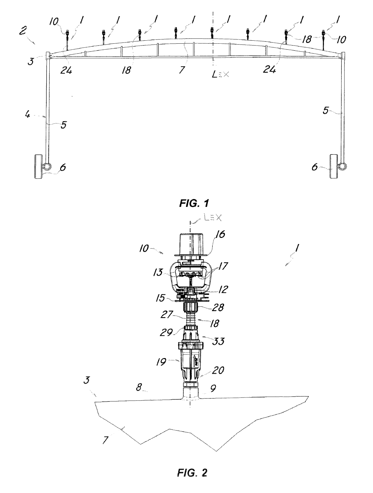
[0041]Particularly referring to the figures, numeral 1 shows and designates a diffuser assembly for distributing a liquid, e.g. water, in irrigation plants 2 having a supply conduit 3.

[0042]The irrigation plant 2 as shown inFIG. 1 may be a pivot or linear irrigation plant and comprises a load-bearing structure 4 with a pair of vertical posts 5 which are adapted to support a substantially horizontal supply conduit 3.

[0043]The posts 5 are wheel-mounted 6, for the lead-bearing structure 4 to be able to move along the portion of the soil to be irrigated and the plant 2 comprises a plurality of diffuser assemblies 1 of the invention, connected to the supply conduit 3.

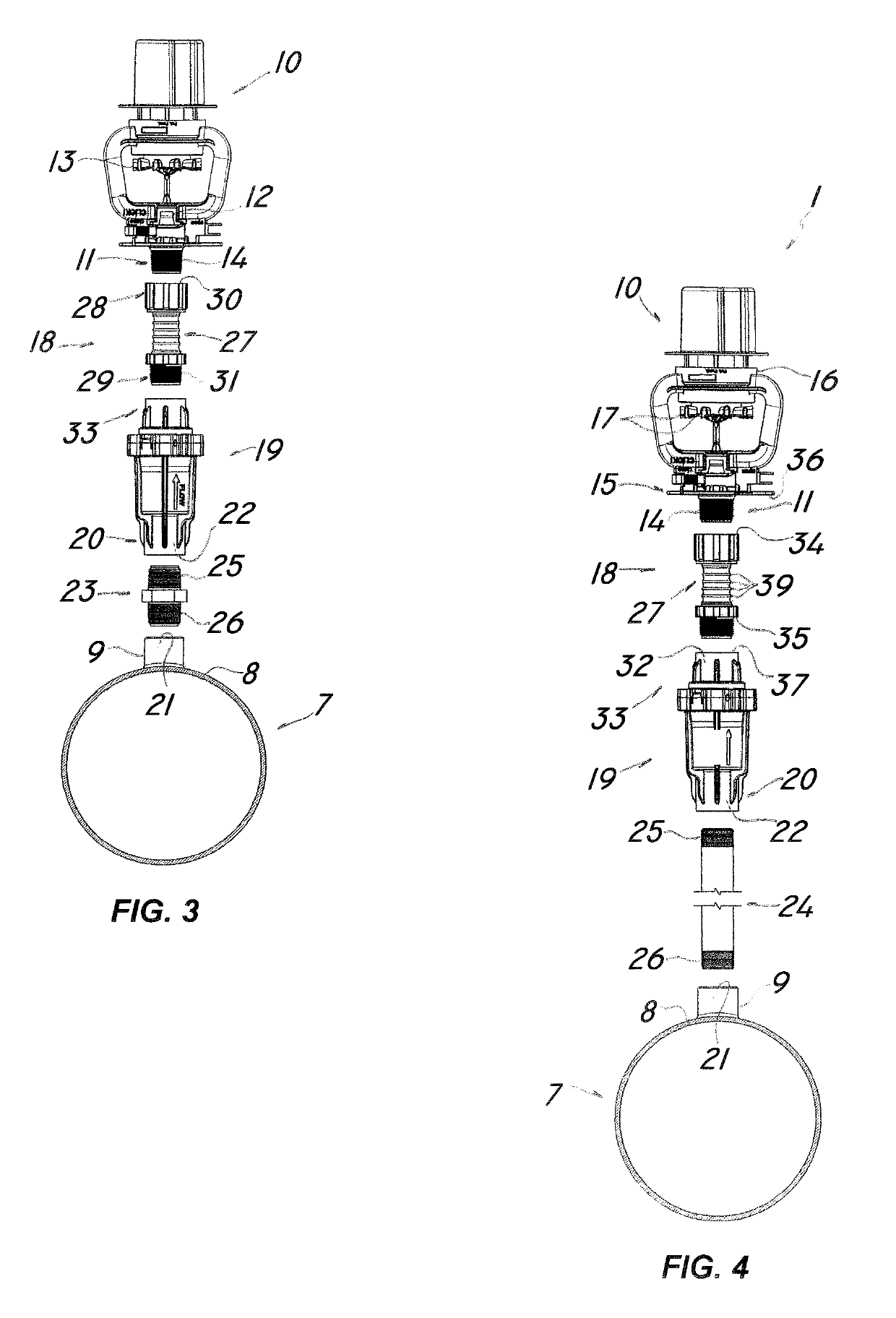
[0044]Furthermore, the supply conduit 3 may comprise a pipe 7 with an upper surface 8 formed with a plurality of first openings 9 for connection to respective diffuser assemblies 1.

[0045]In a preferred embodiment of the invention, the diffuser assembly 1 comprises a diffuser 10 having a second opening 11 for receiving the li...


PUM


Abstract

A diffuser assembly for diffusing a liquid in irrigation plants has a supply conduit includes a diffuser with a nozzle adapted to direct a jet of liquid along a longitudinal axis, at least one deflector facing the nozzle for radially spraying the jet outwards, and a connection device for ensuring fluid connection of the diffuser to the supply conduit of the plant. The diffuser is mounted onto the irrigation plant with the axis extending in a substantially vertical direction and with the nozzle facing up, and the deflector is configured to rotate about the longitudinal axis, thereby causing oscillations in the assembly. The connection device includes a tubular body with end joints that connect to the diffuse, and the supply conduit and the body is monolithic with the joints and is made of a thermoplastic elastomeric base material. Furthermore, the body has an outer surface with annular folds, which imparts elasticity and damp the oscillations induced by the deflector. A pivot or linear irrigation plant includes a plurality of those diffuser assemblies.

Description

FIELD OF THE INVENTION[0001]The present invention generally finds application in the field of irrigation plants for agricultural use, and particularly relates to a diffuser assembly for diffusing a liquid in irrigation plants.[0002]According to a further aspect, the invention relates to a pivot or linear irrigation plant comprising a plurality of the aforementioned diffuser assemblies.BACKGROUND ART[0003]Pivot or linear irrigation plants for agricultural use are known, which comprise a load-bearing structure moving along a portion of the soil to be irrigated, and a liquid supply conduit connected to a plurality of liquid diffuser assemblies, which are mounted to the load-bearing structure.[0004]Each of the liquid diffuser assemblies comprises a diffuser which is adapted to deflect the liquid jet from the supply conduit radially outwards.[0005]Namely, the diffuser comprises a nozzle which is adapted to direct a liquid jet along a longitudinal axis and at least one deflector facing th...

Claims


Application Information

Patent Timeline
Patent Type & Authority Applications(United States)
IPC IPC(8): B05B3/04B05B15/658F16L27/11
CPCB05B3/0486B05B15/658F16L27/11
Inventor DRECHSEL
Owner KOMET AUSTRIA GMBH
Why Eureka
Try Eureka