Method and device in ue and base station used for dynamic scheduling

a dynamic scheduling and wireless communication technology, applied in the direction of signal allocation, digital transmission, transmission path sub-channel allocation, etc., can solve the urgent problem of ensuring the robustness of physical layer control signaling, and the change in directions in which a beam is transmitted or a beam is received, etc., to achieve the effect of improving the reception performance of the second information

Active Publication Date: 2019-08-22
APEX BEAM TECH LLC
View PDF0 Cites 2 Cited by
  • Summary
  • Abstract
  • Description
  • Claims
  • Application Information

AI Technical Summary

Benefits of technology

[0063]In the above aspect, the first information can indicate directions of transmitting beam and receiving beam for the second information simultaneously, which further enhances the reception performance of the second information.

Problems solved by technology

For the Massive MIMO, however, changes in directions in which a beam is transmitted or a beam is received may be very fast due to rotation or movement of a UE.
Therefore, how to guarantee robustness of a physical layer control signaling becomes an urgent problem to be solved.

Method used


Image

  • Method and device in ue and base station used for dynamic scheduling
  • Method and device in ue and base station used for dynamic scheduling
  • Method and device in ue and base station used for dynamic scheduling

Examples


embodiment 1

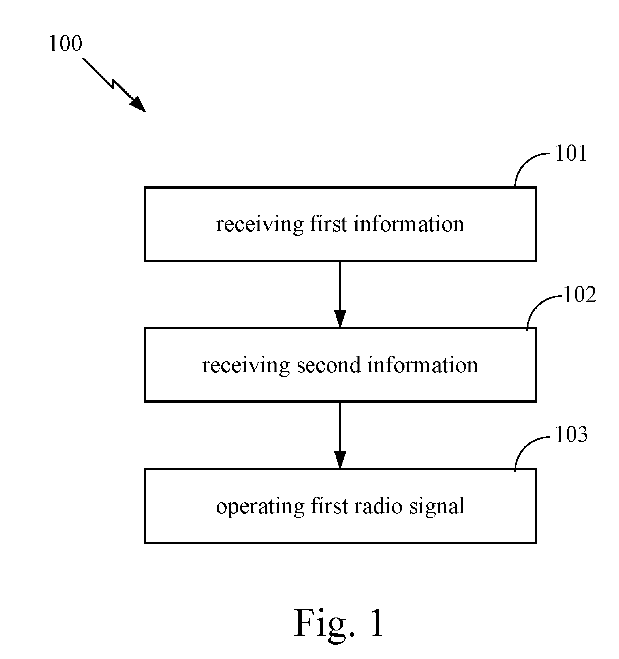
[0154]Embodiment 1 illustrates a flowchart of transmission of first information, second information and a first radio signal according to one embodiment of the present disclosure, as shown in FIG. 1. In FIG. 1, each block represents a step. In Embodiment 1, a UE in the present disclosure first receives first information, and then receives second information, and operates a first radio signal; wherein the first information comprises Q field(s), the Q field(s) corresponds(correspond) to Q target receiver(s) respectively, the UE is a target receiver out of the Q target receiver(s); a first field out of the Q field(s) corresponds to the UE, the first field is used to determine a first antenna port set, the first field is a field of the Q field(s); the first antenna port set comprises a positive integer number of antenna port(s), the second information is transmitted by antenna port(s) within the first antenna port set; the first information and the second information are both dynamicall...

embodiment 2

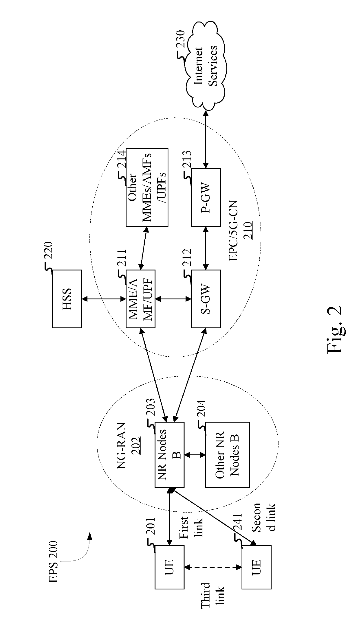
[0163]Embodiment 2 illustrates a schematic diagram illustrating a network architecture according to the present disclosure, as shown in FIG. 2. FIG. 2 is a diagram illustrating a network architecture 200 of NR 5G, Long-Term Evolution (LTE) and Long-Term Evolution Advanced (LTE-A) systems. The NR 5G or LTE network architecture 200 may be called an Evolved Packet System (EPS) 200. The EPS 200 may comprise one or more UEs 201, an NG-RAN 202, an Evolved Packet Core / 5G-Core Network (EPC / 5G-CN) 210, a Home Subscriber Server (HSS) 220 and an Internet Service 230. The EPS may be interconnected with other access networks. For simple description, the entities / interfaces are not shown. As shown in FIG. 2, the EPS 200 provides packet switching services. Those skilled in the art will find it easy to understand that various concepts presented throughout the present disclosure can be extended to networks providing circuit switching services or other cellular networks. The NG-RAN 202 comprises an N...

embodiment 3

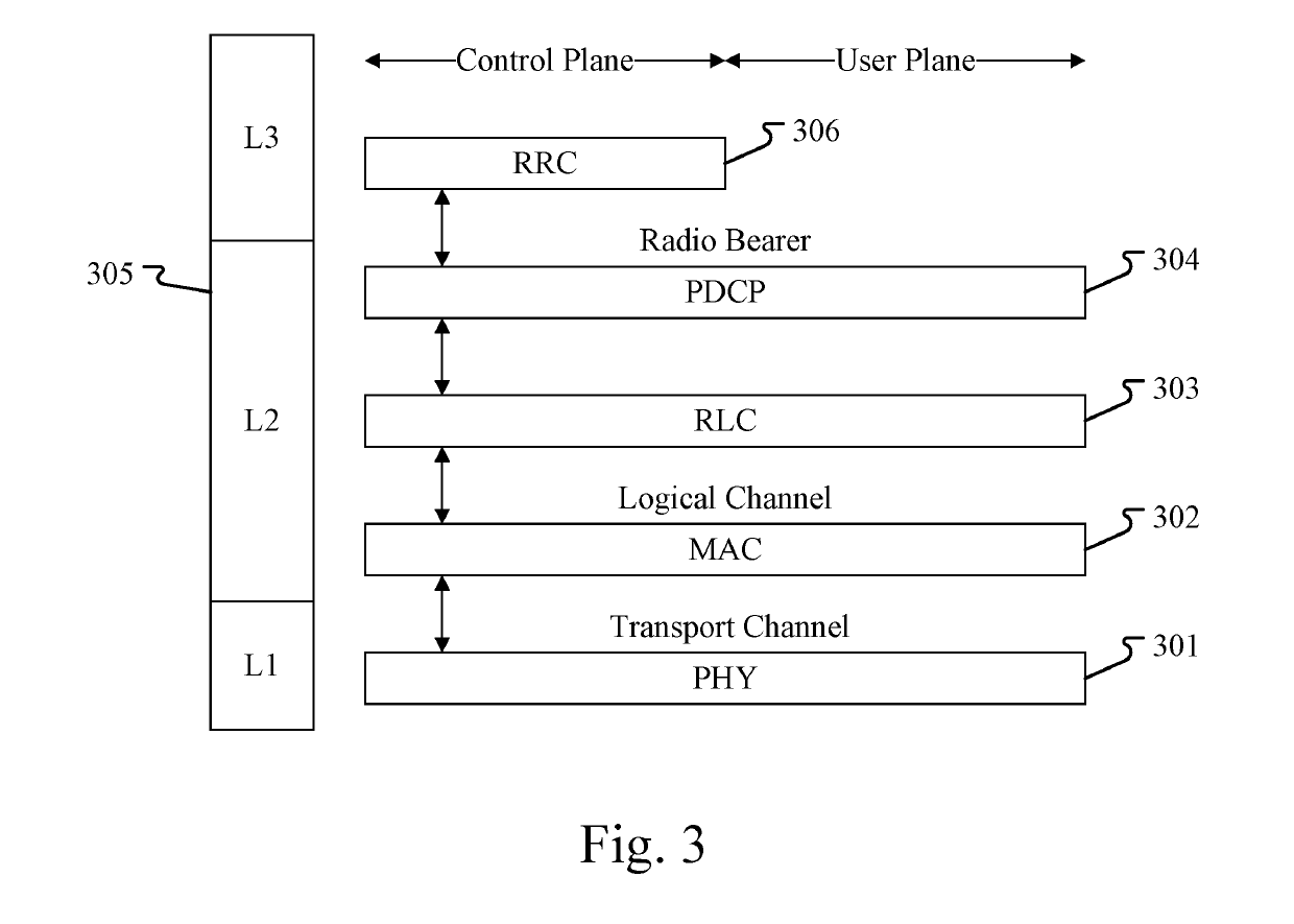
[0168]Embodiment 3 illustrates a schematic diagram of an embodiment of a radio protocol architecture of a user plane and a control plane according to the present disclosure, as shown in FIG. 3. FIG. 3 is a schematic diagram illustrating an embodiment of a radio protocol architecture of a user plane and a control plane. In FIG. 3, the radio protocol architecture for a UE and a gNB is represented by three layers, which are a layer 1, a layer 2 and a layer 3, respectively. The layer 1 (L1) is the lowest layer and performs signal processing functions of various PHY layers. The L1 is called PHY 301 in the present disclosure. The layer 2 (L2) 305 is above the PHY 301, and is in charge of the link between the UE and the gNB via the PHY 301. In the user plane, L2 305 comprises a Medium Access Control (MAC) sublayer 302, a Radio Link Control (RLC) sublayer 303 and a Packet Data Convergence Protocol (PDCP) sublayer 304. All the three sublayers terminate at the gNBs of the network side. Althou...


PUM


Abstract

The present disclosure provides a method and device in User Equipment and a base station for dynamic scheduling. The UE first receives first information; and then receives second information; and operates a first radio signal. The first information comprises Q fields, a first field is used to determine a first antenna port set, and the first field is one field of the Q fields. The first antenna port set comprises a positive integer of antenna port(s), the second information is transmitted by an antenna port within the first antenna port set. The first information and the second information are both dynamically configured. The Q is a positive integer. The operating refers to receiving or transmitting. The second information is determined scheduling information of the first radio signal. The method ensures the robustness of scheduling signaling reception in multi-antenna scenarios, avoids excessive overhead, and improves transmission efficiency.

Description

CROSS REFERENCE TO RELATED APPLICATION[0001]This application is a continuation of International Application No. PCT / CN2017 / 108033, filed Oct. 27, 2017, claiming the priority benefit of Chinese Patent Application Serial Number 201610936764.0, filed on Nov. 1, 2016, the full disclosure of which is incorporated herein by reference.BACKGROUNDTechnical Field[0002]The present disclosure relates to dynamic scheduling schemes in wireless communication systems, and in particular to scheduling schemes for wireless communication systems using multi-antenna technology.Related Art[0003]Massive Multi-Input Multi-Output (MIMO) becomes a hot topic when studying next generation mobile communications. For the massive MIMO, multiple antennas based on beamforming form a narrow beam which points to a particular direction to improve the quality of communication. Since a beam formed by beamforming of multiple antennas is usually narrow, each side of the communication requires part of the other side's chan...

Claims


Application Information

Patent Timeline
Patent Type & Authority Applications(United States)
IPC IPC(8): H04W72/04H04W72/12
CPCH04W72/046H04W72/1278H04W72/0466H04B7/0413H04W72/1263H04L5/0092H04L5/0053H04L5/0023H04B7/0617H04B7/0848H04W72/23H04W72/12H04W72/20
Inventor ZHANG, XIAOBO
Owner APEX BEAM TECH LLC
Why Eureka
Try Eureka