High efficiency stripper nozzle

a stripper nozzle, high-efficiency technology, applied in metal extrusion, chemistry apparatus and processes, manufacturing tools, etc., can solve the problems of affecting the operation of the stripper nozzle, the loss of fluid becomes a financial loss, and the additional maintenance expense, so as to avoid leakage

Pending Publication Date: 2019-08-29
NORTEK SA
View PDF10 Cites 0 Cited by
  • Summary
  • Abstract
  • Description
  • Claims
  • Application Information

AI Technical Summary

Benefits of technology

[0008]The present high-efficiency stripper nozzle is a new development in the field of application that resolves the problems mentioned above. It was developed in order to provide a way to a

Problems solved by technology

One of the main problems in existing systems is the containment of the coolant/lubricant fluid.
Due to the nature of the process, it is difficult to ensure that the pressurized fluid will stay within the limits of the system.
Any loss of fluid becomes a financial loss and an additional maintenance expense, because it could affect the functioning of other components on the production line and create demand for additional repairs of other mechanical or electrical equipment.
It may also become a potential safety, environmental, and operational risk, or a limiting factor for the measurement of the efficiency o

Method used


Image

  • High efficiency stripper nozzle

Examples


Embodiment Construction

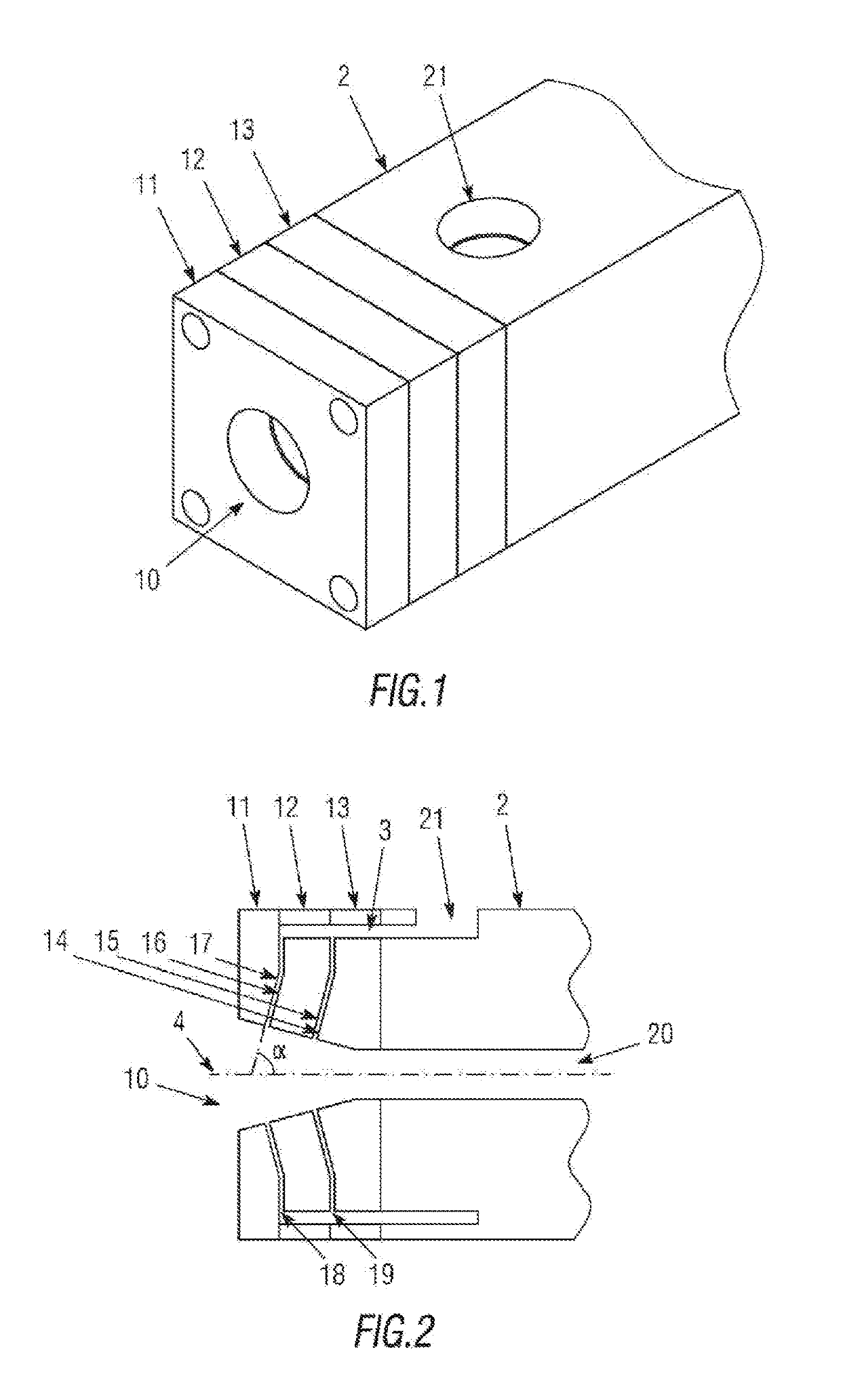
[0021]The aforementioned figures, according to the adopted numbering, show a preferred embodiment of the invention, which comprises the parts and elements that are indicated and described in detail below.

[0022]As shown in FIG. 1, one possible embodiment of the present stripper nozzle is divided into a set of three pieces (11, 12, 13), arranged in series and attached to a nozzle (2), whose through hole (20) is connected to the through hole (10) of the stripper nozzle, in this case with a cone-shaped entrance.

[0023]In this embodiment, the internal contact walls (14, 15, 16, 17) between the pieces (11, 12, 13) have an angled cross-section with respect to the axis (4) of the hole (10), with a conical angle (α) of 15°. The walls comprise gaps such that between them, radial channels (18, 19) are formed, which emerge, on one hand, at the entrance of the through hole (10), and on the other, are connected to the opening (21) located on one of the longitudinal faces of the nozzle (2) by means...


PUM

PropertyMeasurementUnit
Angleaaaaaaaaaa
Efficiencyaaaaaaaaaa
Perimeteraaaaaaaaaa

Abstract

A high efficiency stripper nozzle, with a through hole configured to be connected to the through hole of another nozzle, guide, or nozzle, which comprises several radial channels that pass through the nozzle from the perimeter zone to the hole at its entrance zone. The nozzle may be divided into several pieces which can be connected together in a removable way and replaceable, which may form the radial channels between them with different sections and angles with respect to the axis of the hole. The radial channels may contact externally with an opening located on one of the surfaces of the nozzle or on one of the surfaces of the nozzle to which the nozzle is connected.

Description

RELATED APPLICATION[0001]This application claims the benefit of priority of Spanish Patent Application No. 201830186 filed Feb. 27, 2018, the contents of which are incorporated herein by reference in their entirety.FIELD AND BACKGROUND OF THE INVENTION[0002]The purpose of the present application is to register a stripper nozzle that incorporates significant advantages over those used to date, particularly convenient for refrigeration and / or lubrication processes during the production of metal products with continuous longitudinal shapes, such as wire, rods, or bars.[0003]More specifically, the invention proposes a stripper nozzle with radial channels which, due to their specific geometry, restrain the circulation of the coolant and / or lubricant that accompanies the metal product being produced, preventing leaks and excessive flow of said fluid.[0004]Cooling and / or lubrication systems for the processing of metal in continuous longitudinal shapes are known. The processing requires the...

Claims


Application Information

Patent Timeline
IPC IPC(8): B21C43/02B21C35/06
CPCB21C43/02B08B5/023B05B1/28B21C35/06B21B45/0224B21B45/0257B05B1/00
Inventor LAZO, JOSE RAFAELGASPARIK, JOHN PAUL
Owner NORTEK SA
Why Eureka
Try Eureka