
Apparatus for detecting or monitoring for a chemical precursor in a high temperature environment

a technology of chemical precursors and apparatus, which is applied in the direction of instruments, analysis by electrical excitation, plasma techniques, etc., can solve the problems of clogging of gas pathways, adverse particle formation of film formed in reaction chambers, and defect of apparatus,

Active Publication Date: 2019-08-29
ASM IP HLDG BV
View PDF0 Cites 223 Cited by
  • Summary
  • Abstract
  • Description
  • Claims
  • Application Information

AI Technical Summary

Benefits of technology

The patent text describes an apparatus and method for detecting or monitoring the concentration of a chemical in a high temperature environment. The technical effect of this invention is to provide a better understanding of the chemicals used in chemical vapor deposition and atomic layer deposition processes, and to prevent defects and clogging issues that can occur in the gas pathways of the reaction chamber. The invention allows for the monitoring of chemical concentrations in real-time, which can help to improve process control and stability.

Problems solved by technology

Defects may occur due to condensation of heated chemistries along a gas pathway to the reaction chamber.
The condensation of the heated chemistries may lead to a chemical reaction within the gas pathway prior to reaching the reaction chamber, leading to adverse particle formation on the film formed within the reaction chamber.
In addition, clogging may occur within the gas pathways due to the condensation.
Clogging may result in shutting down operation of the reaction chamber in order to clear the gas pathways, as well as exacerbate the particle formation that adversely affects the film formed in the chamber.
In addition, changes to process conditions may affect the deposition onto the wafer; for example, a change in temperature or pressure may lead to shifts in non-uniformities as it relates to film properties.
These process shifts may lead to non-uniformities in thickness or concentration of the film, potentially resulting in scrapped wafers.
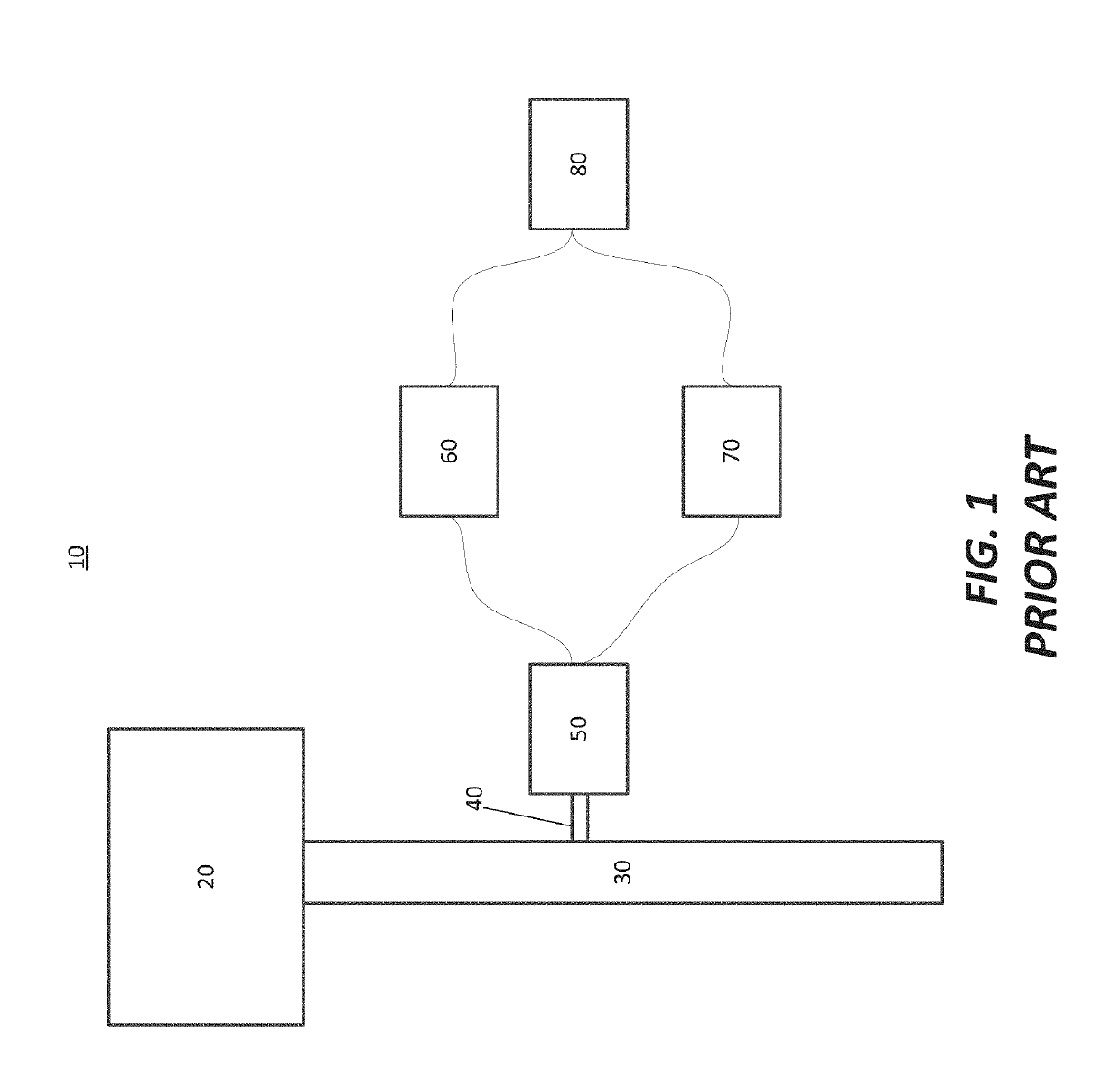
Prior art approaches to monitor concentrations of chemistries have been limited to temperatures less than 60-80° C. At these temperatures, condensation of gaseous precursors may occur, leading to the above described problems.

Method used


Image

  • Apparatus for detecting or monitoring for a chemical precursor in a high temperature environment
  • Apparatus for detecting or monitoring for a chemical precursor in a high temperature environment
  • Apparatus for detecting or monitoring for a chemical precursor in a high temperature environment

Examples


Embodiment Construction

[0017]Although certain embodiments and examples are disclosed below, it will be understood by those in the art that the invention extends beyond the specifically disclosed embodiments and / or uses of the invention and obvious modifications and equivalents thereof. Thus, it is intended that the scope of the invention disclosed should not be limited by the particular disclosed embodiments described below.

[0018]As used herein, the term “substrate” may refer to any underlying material or materials that may be used, or upon which, a device, a circuit or a film may be formed.

[0019]As used herein, the term “chemical vapor deposition” (CVD) may refer to any process wherein a substrate is exposed to one or more volatile precursors, which react and / or decompose on a substrate surface to produce a desired deposition.

[0020]As used herein, the term “atomic layer deposition” (ALD) may refer to a vapor deposition process in which deposition cycles, preferably a plurality of consecutive deposition c...


PUM

PropertyMeasurementUnit
Flow rateaaaaaaaaaa
Chemically inertaaaaaaaaaa

Abstract

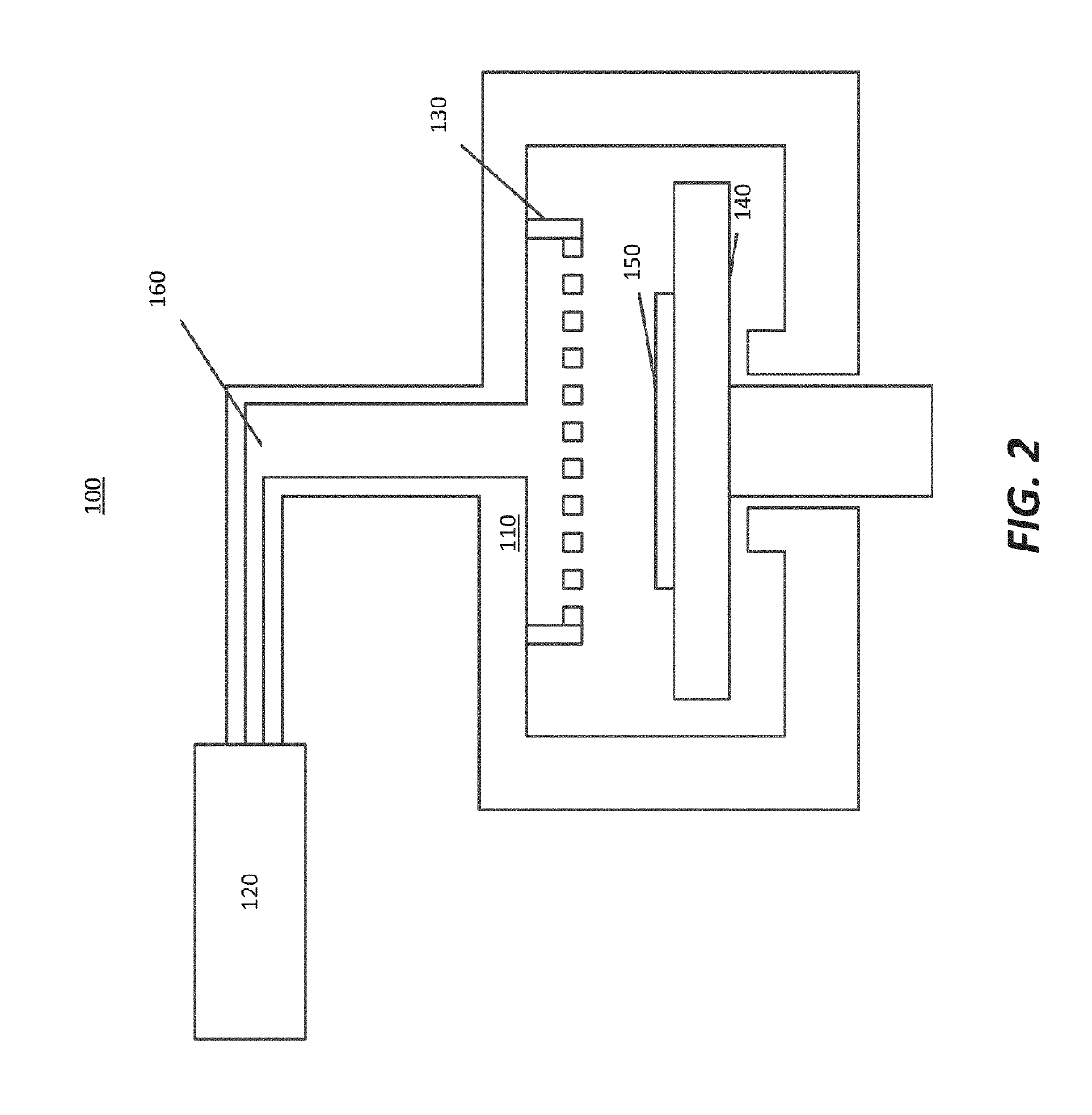
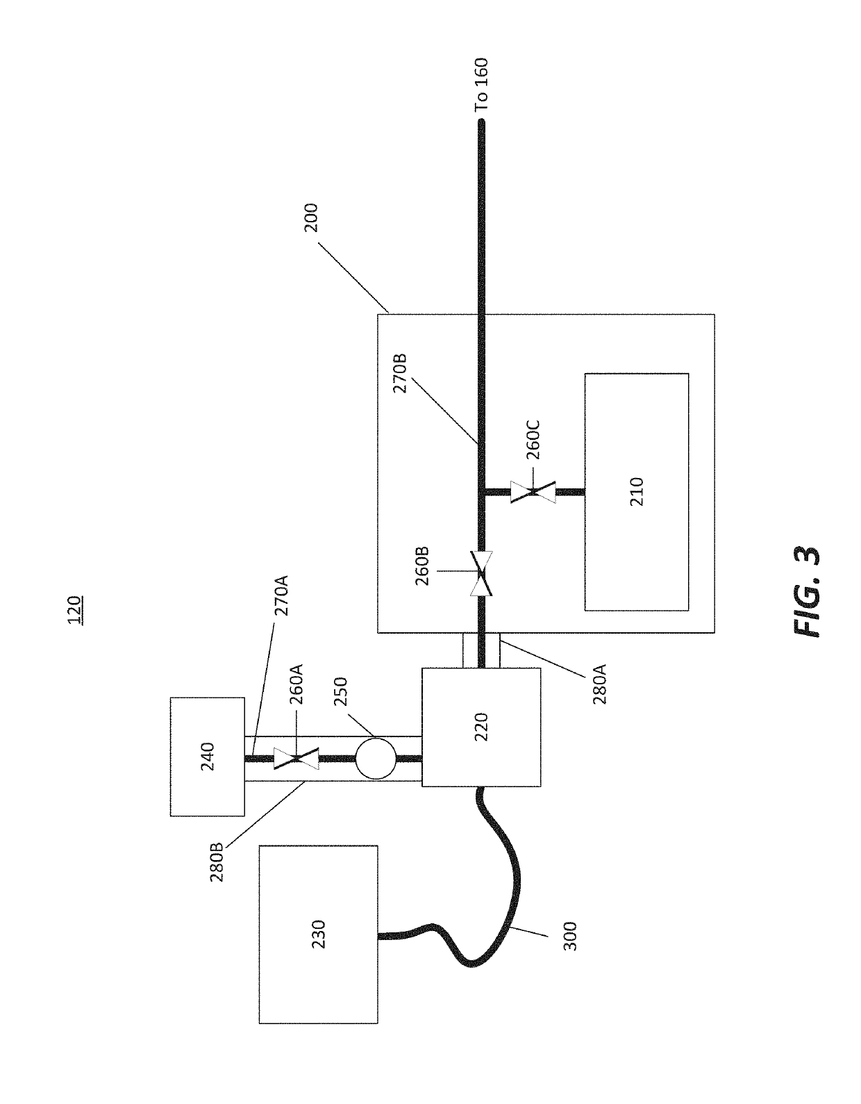
An apparatus and method are disclosed for monitoring and / or detecting concentrations of a chemical precursor in a reaction chamber. The apparatus and method have an advantage of operating in a high temperature environment. An optical emissions spectrometer (OES) is coupled to a gas source, such as a solid source vessel, in order to monitor or detect an output of the chemical precursor to the reaction chamber. Alternatively, a small sample of precursor can be periodically monitored flowing into the OES and into a vacuum pump, thus bypassing the reaction chamber.

Description

CROSS-REFERENCE TO RELATED APPLICATION[0001]This application claims the benefit of U.S. Provisional Application No. 62 / 634,793 entitled “APPARATUS FOR DETECTING OR MONITORING FOR A CHEMICAL PRECURSOR IN A HIGH TEMPERATURE ENVIRONMENT” and filed on Feb. 23, 2018, the disclosure of which is hereby incorporated herein for reference.FIELD OF INVENTION[0002]The present disclosure generally relates to an apparatus for forming a film on a semiconductor substrate. Specifically, the present disclosure relates to a chemical source for the apparatus and detecting or monitoring a concentration of a gas provided by the chemical source.BACKGROUND OF THE DISCLOSURE[0003]Chemical Vapor Deposition (CVD) and Atomic Layer Deposition (ALD) are both processes used to form a film on a semiconductor substrate disposed within a reaction chamber. The processes may involve flow of a first gas onto the substrate and flow of a second gas onto the substrate, such that the first gas reacts with the second gas in...

Claims


Application Information

Patent Timeline
IPC IPC(8): C23C16/455H01J37/32C23C16/505G01N21/68G01J3/443
CPCC23C16/45536H01J37/3244H01J37/32972C23C16/505H01J2237/24485G01N21/68G01J3/443H01J2237/24507C23C16/45544G01N21/73G01N21/15G01N2201/08C23C16/448C23C16/455H01L21/67242H01L21/67017H01L21/67098H05H1/46G01N21/31
Inventor SHUGRUE, JOHNWHITE, CARL
Owner ASM IP HLDG BV
Learn More