[0017]The present invention has numerous advantages including those now specifically described. Other advantages will be apparent from the description below. The present invention allows a more controlled separation in time of the different phases in the spark process. For example, the invention allows a better separation of the phase of pre-treatment (re-melting and structure refining) and vaporisation of the sample surface from the phase of excitation of the
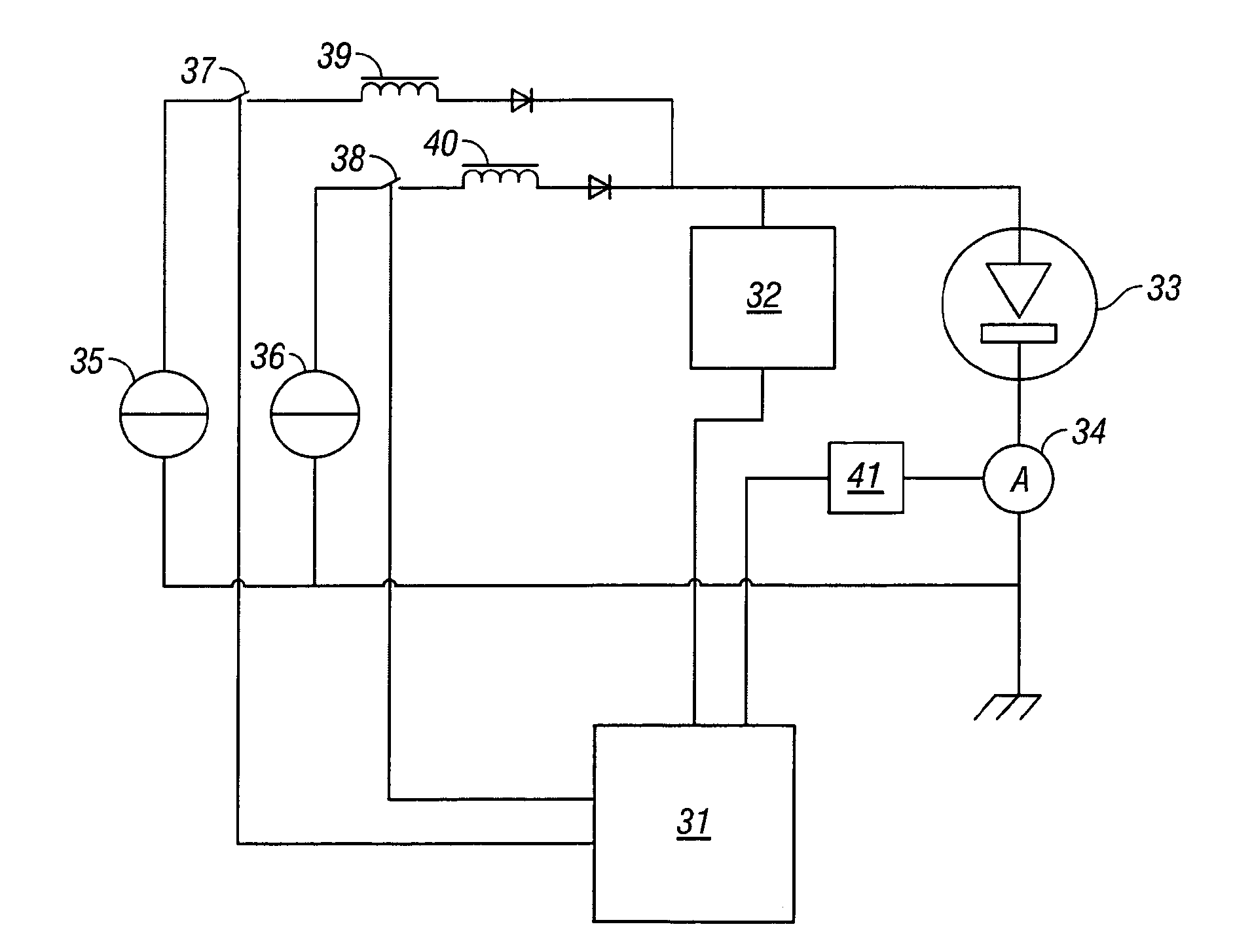
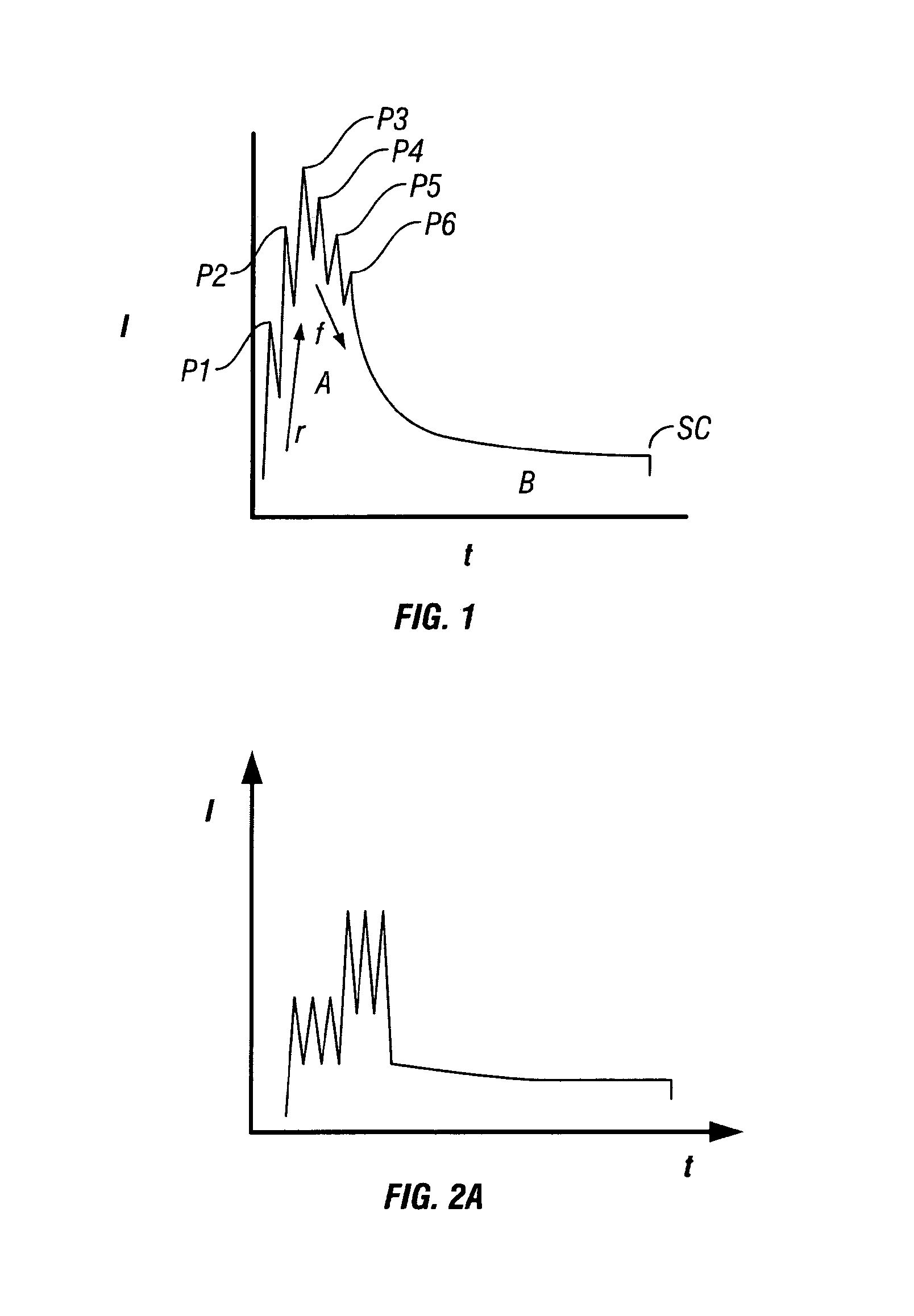
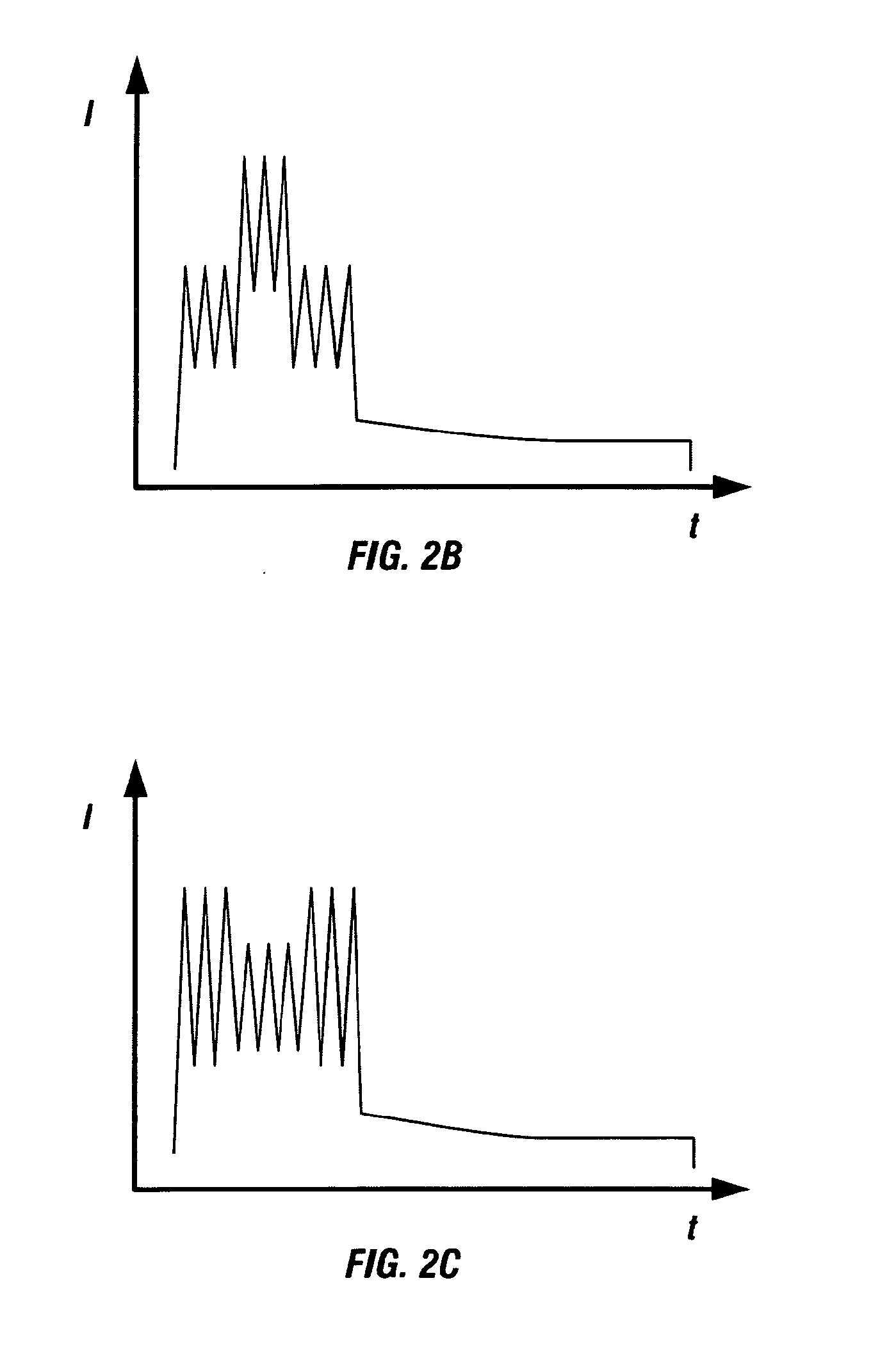
resultant vapours for optical analysis. The use of programmable current sources permits variation of the inter-peak duration, the
rise time, the peak amplitude and the number of
high current peaks. This degree of control is not possible with either the cascaded current sources of JP 8-159973 A and EP 318 900 A2 or the decaying oscillatory
current source of EP 84566 A.
[0020]The invention enables the determination with good precision of both trace elements and alloying elements in
metal samples, in contrast to the prior art methods described above which are better suited to either one of these applications or the other. As with other spark sources, a part of the spark's energy will be used for sample evapouration, a part for atomisation and / or ionisation and a part for excitation However, without the scope of the present invention being bound by any particular theory, the invention may achieve the
advantage above because the spark energy is delivered in a plurality of relatively
high current high gradient current peaks (i.e.
high energy), e.g. in the early part of the waveform, compared to the purely analogue spark source, thus creating more controlled higher temperature zones in the
plasma, e.g. which may be of 7,000-10,000K, which favour
high energy electron transitions in atomic and ionic species. The most sensitive spectral lines, which can be useful in determining trace elements, typically arise from the so-called
resonance transitions, such as atomic type transitions (described in tables of spectral lines as U1, U2, . . . etc.) and ionic type transitions (described in tables of spectral lines as V1, V2, . . . etc.). These have high transition probabilities and can have high energies, e.g. in the range of 7 to 12 eV, and thus are most efficiently excited by the high temperature
plasma. In particular, the use of a plurality of peaks in the high current part of the waveform, which is preferably programmable, of variable amplitude and / or inter-peak duration gives a better degree of control of the duration of the high temperature
plasma.
[0021]Similarly, without the scope of the invention being bound by any theory, the detection of alloying elements in metals may be enhanced, compared to the prior art digital spark source described in EP 396 291 B1, because the spark energy is not concentrated into a single, highly intense current peak at the beginning of the waveform but instead is spread over a plurality of peaks of variable amplitude and / or inter-peak duration so that the waveform is also efficient at promoting lower energy
electron transitions (e.g. 2 to 7 eV) which tend to occur later in the spark, mainly in
atomic species, and it creates a lower background for these transitions. These types of atomic transitions are often less sensitive, i.e. having lower transition probabilities, and as such can be useful in determining alloying elements which otherwise would, due the
high concentration of the elements present, produce highly intense spectral lines that could overload the
detector.
[0022]Due to the improved control over the
energy delivery to the spark plasma, a better time separation of the excitation conditions favourable for
high energy transitions (e.g. 7-12 eV) on the one hand and the excitation conditions favourable for low energy transitions (e.g. 2-7 eV) on the other can be achieved with the present invention. The invention also allows better separation of the spectral background (also termed continuum
radiation) from the useful transitions. These features benefit the use of so-called “time-resolved
spectroscopy” (TRS) often used in OES in which the emitted light is measured only within a defined time window located within the spark duration. TRS may also be termed Time Gated
Spectroscopy (TGS). Different
time windows can be employed in TRS for different spectral lines. The choice of time window depends on the parameters of the
spectral line such as its energy. The time window can also be chosen to minimise perturbations to the
spectral line from, e.g., the source or spectral background interference. TRS is, for example, of significant benefit for
trace element analysis.
[0023]The present invention has been found to significantly improve precision in the
quantitative determination of many compositions (for a given
acquisition time) and thereby reduce acquisition times for the same precision.
[0024]The use of a spark having a waveform in accordance with the present invention can reduce the rate of deterioration of the response of a CCD
light detector in the environment of an OES instrument. Without being bound by any theory, it is believed that the deterioration is due to a photochemical reaction (“
quenching”) of volatile
organic molecules, which are typically present in the low pressure environment of the instrument in small amounts, with intense UV light, such as is produced when using the single intense current peak of the prior art digital spark source. The photochemically produced products are then thought to become deposited on the surface of the
CCD detector, which lowers the
detector sensitivity over time. The present invention uses a spark which spreads the high energy over a plurality of peaks of variable amplitude and / or inter-peak duration rather than concentrate the energy into the single intense peak as in the prior art and this is believed to reduce the
quenching probability and thereby explaining the observed reduction of the
deposition rate on the
detector when used with the present invention.


