Vacuum-pump rotor

Inactive Publication Date: 2019-08-29
LEYBOLD HERAEUS GMBH & CO KG
View PDF0 Cites 0 Cited by
  • Summary
  • Abstract
  • Description
  • Claims
  • Application Information

AI Technical Summary

Benefits of technology

[0013]According to another preferred embodiment, a surface of the at least one displacement element is provided with an emergency operation coating. Here, it is preferred that only those surfaces of the displacement element are provided with such a coating, which may come into contact with another displacement element during operation. Provision of such an emergency operation coating on the basis of PTFE or molybdenum sulfite, for example, offers the advantage that the coating s

Problems solved by technology

Due to the hardness of steel and cast iron, the processing of the corresponding vacuum pump rotors, for producing a helical groove on a rotor for a screw pump, for example, is complicated and expensive.
In particular, high tooling costs are involved.
Vacuum pump rotors from different materials involve a considerable manufacturing effort since the two components must be joined t

Method used


Image

  • Vacuum-pump rotor

Examples


Example

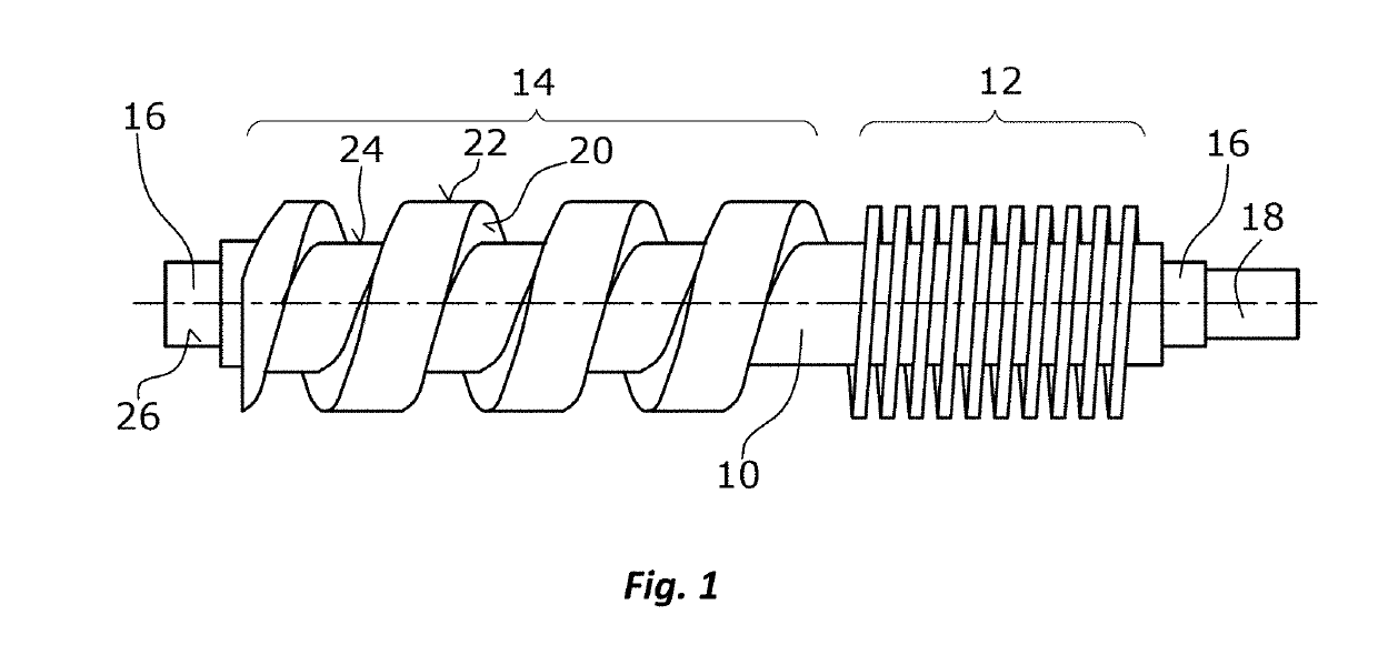
[0016]Hereunder the disclosure is described on the basis of an exemplary screw rotor, wherein the disclosure is in particular also applicable to rotors for claw pumps, Roots pumps and multistage claw and Roots pumps.

[0017]In the illustrated exemplary embodiment, a vacuum pump rotor of a screw pump comprises a rotor shaft 10 on which two displacement elements 12, 14 are arranged. In particular, the rotor shaft 10 and the displacement elements 12, 14 are integrally formed. In the illustrated exemplary embodiment, the two displacement elements 12, 14 have different pitches, wherein the displacement element 14 having a larger pitch is connected to the inlet of the vacuum pump on the left-hand side in the Figure and the displacement element 12 having the smaller pitch is connected to the outlet of the vacuum pump on the right-hand side in the Figure.

[0018]In the illustrated exemplary embodiment, the rotor shaft 10 comprises two shaft ends 16 since this is a vacuum pump rotor mounted on b...


PUM

PropertyMeasurementUnit
Fractionaaaaaaaaaa
Displacementaaaaaaaaaa
Thermal expansion coefficientaaaaaaaaaa

Abstract

A vacuum pump rotor comprises at least one displacement element arranged on a rotor shaft. The rotor shaft comprises at least one shaft end for a bearing element to be arranged thereon. The rotor element, the at least one displacement element and the at least one shaft end are made from aluminum or an aluminum alloy.

Description

BACKGROUND1. Field of the Disclosure[0001]The disclosure relates to a vacuum pump rotor, in particular for screw pumps, claw pumps, Roots pumps and multistage claw and Roots pumps.2. Discussion of the Background Art[0002]Rotors are usually made from steel or cast iron. Here, the rotor comprises a rotor shaft having one or a plurality of displacement elements, wherein the displacement elements are of different configurations according to the pump type. Here, the rotor shaft and the displacement elements are integrally formed from steel or cast iron. Due to the hardness of steel and cast iron, the processing of the corresponding vacuum pump rotors, for producing a helical groove on a rotor for a screw pump, for example, is complicated and expensive. In particular, high tooling costs are involved.[0003]Further, vacuum pump rotors for screw pumps are known, where the shaft is made from steel and supports a displacement element made from aluminum. Vacuum pump rotors from different materi...

Claims


Application Information

Patent Timeline
IPC IPC(8): F04C3/00F04C15/00
CPCF04C2220/10F05C2201/903F05C2201/0448F05C2251/042F05C2253/12F05C2201/021F04C15/00F04C2240/20F04C2250/20F04C3/00
Inventor DREIFERT, THOMASSCHILLER, DIRKGIEBMANNS, WOLFGANGMÜLLER, ROLAND
Owner LEYBOLD HERAEUS GMBH & CO KG
Why Eureka
Try Eureka