Display device having touch sensors and driving method thereof

a technology of touch sensor and display device, which is applied in semiconductor devices, instruments, computing, etc., can solve the problems of parasitic effects, difficult to secure enough time for in-cell touch sensor technology, and distortion of touch sensing signals, so as to improve touch sensing signal sensitivity, improve the effect of picture quality of display images, and minimize parasitic effects

Active Publication Date: 2019-08-29
LG DISPLAY CO LTD
View PDF8 Cites 7 Cited by
  • Summary
  • Abstract
  • Description
  • Claims
  • Application Information

AI Technical Summary

Benefits of technology

[0011]The present invention has been made in an effort to provide a display device which improves touch sensitivity and the picture quality of display images by overlapping a touch interval and a display interval, which improves touch sensing signal sensitivity by minimizing the effects of parasitic capacitance formed by signal lines for display and touch sensors, and a driving method thereof.

Problems solved by technology

Since the in-cell touch sensor technology uses segmented common electrode patterns as electrodes of the touch sensors, display noise may be mixed in with a touch sensing signal when the touch sensors are driven while input image data is being written to pixels, which can distort the touch sensing signal.
However, the in-cell touch sensor technology is difficult to secure enough time for sufficient touch and display intervals Tt and Td within one frame period because of time-division driving.
This problem gets more severe as resolution and frame frequency increase.
If the display interval Td is not sufficient, this leads to lack of data charging time for driving the display, thereby deteriorating the picture quality of display images.
The add-on type and the on-cell type do not lack sufficient touch and display intervals because the touch interval and the display interval are not temporally separated but overlap.
However, in a display device having add-on type or on-cell type touch sensors, signal lines for display and the touch sensors form parasitic capacitance, which can attenuate the touch sensing signal and therefore decrease touch sensitivity.

Method used


Image

  • Display device having touch sensors and driving method thereof
  • Display device having touch sensors and driving method thereof
  • Display device having touch sensors and driving method thereof

Examples


Embodiment Construction

[0031]Hereinafter, exemplary embodiments of the present invention will be described in detail with reference to the attached drawings. Throughout the specification, like reference numerals denote substantially like components. In describing the present invention, a detailed description of known functions or configurations related to the present invention will be omitted when it is deemed that they may unnecessarily obscure the subject matter of the present invention.

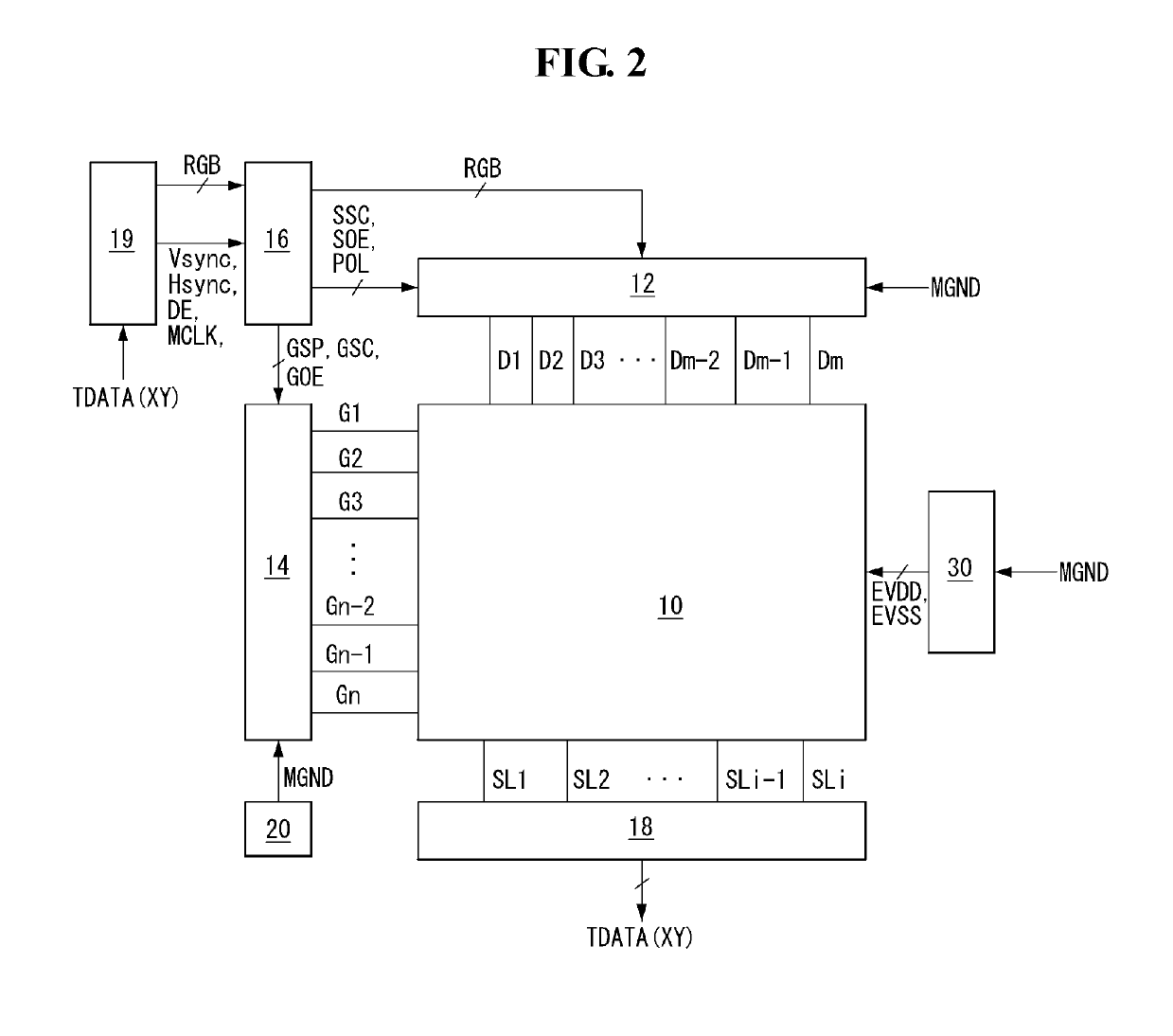
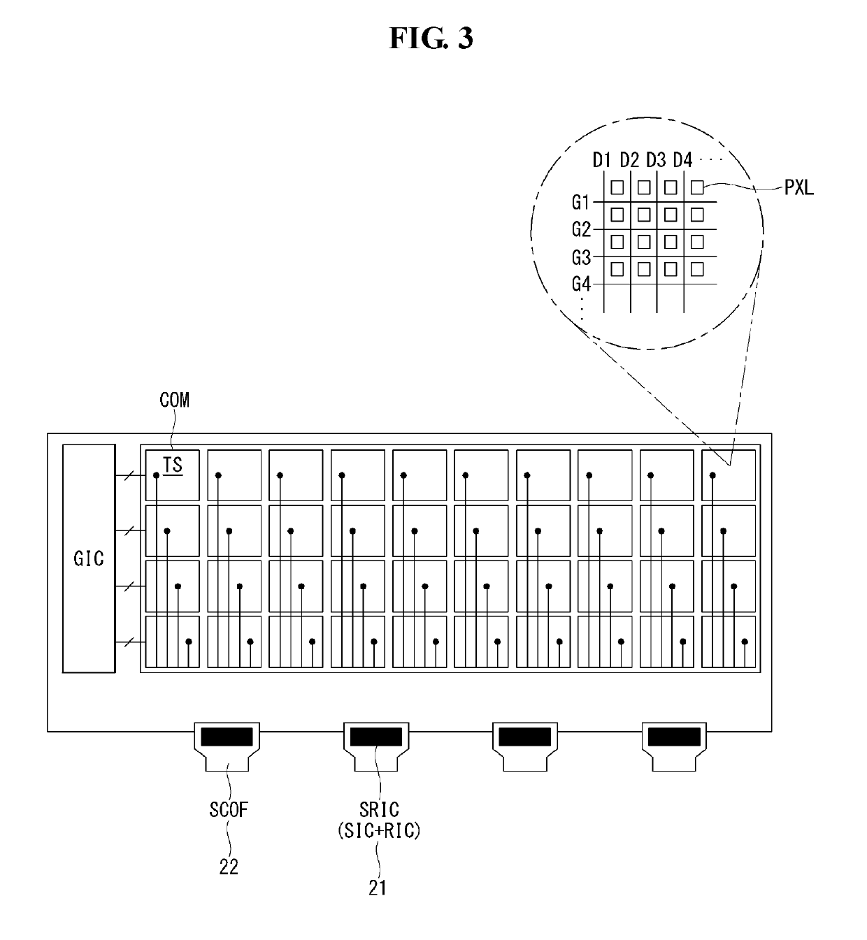
[0032]FIG. 2 shows a display device having touch sensors according to an exemplary embodiment of the present invention. FIG. 3 shows a liquid crystal display with built-in touch sensors according to one exemplary embodiment of the present invention. FIGS. 4 to 6 show on-cell type touch sensors integrated with an organic light-emitting display according to another exemplary embodiment of the present invention. FIG. 7 shows an overall configuration for controlling the supply of a ground signal and a modulated ground signal...


PUM

PropertyMeasurementUnit
driving voltageaaaaaaaaaa
voltageaaaaaaaaaa
phaseaaaaaaaaaa

Abstract

A display device can include an organic light emitting layer positioned between an anode electrode and a cathode electrode; an encapsulation layer disposed on the organic emission layer to protect the organic emission layer; a touch layer disposed on the sealing layer, the touch layer having a plurality of touch sensors configured to be driven according to a touch driving signal; a ground modulation signal generator configured to generate a ground modulation signal having a same amplitude as an amplitude of the touch driving signal; and a driving voltage supply configured to generate a modulated driving voltage based on the ground modulation signal, and apply the modulated driving voltage to a driving voltage supply line in synchronization with the touch driving signal within a same display frame.

Description

CROSS REFERENCE TO RELATED APPLICATIONS[0001]This application is a Continuation of U.S. patent application Ser. No. 15 / 639,439 filed Jun. 30, 2017, which claims the priority benefit of Korean Patent Application Nos. 10-2016-0083077 and 10-2016-0126705 filed in the Republic of Korea on Jun. 30, 2016, and Sep. 30, 2016, respectively, all of these applications are incorporated herein by reference for all purposes as if fully set forth herein.BACKGROUND OF THE INVENTIONField of the Invention[0002]The present invention relates to a display device having touch sensors and a driving method thereof.Discussion of the Related Art[0003]User interfaces (UI) enable humans (users) to easily control various types of electronic devices as they want. Typical examples of the user interfaces include keypads, keyboards, mice, on-screen displays (OSD), and remote controllers with an infrared communication capability or radio frequency (RF) communication capability. The user interface technology is conti...

Claims


Application Information

Patent Timeline
Patent Type & Authority Applications(United States)
IPC IPC(8): G06F3/041G09G3/3266G02F1/1362G06F3/044G02F1/1333G09G3/3275G09G3/36H01L27/32
CPCG06F3/0416G09G3/3266G02F1/136286G06F3/0412H01L27/323G02F1/13338G09G3/3275G09G3/3688G06F3/044G09G3/3677G06F3/0418G06F3/0443G06F3/04166G06F3/04164G09G3/3233G09G2354/00G09G2300/0842G06F3/04184H10K59/40
Inventor SHIN, SEUNGROKLEE, DEUKSUKIM, SANGKYULEE, JAEGYUNKIM, TAEYUN
Owner LG DISPLAY CO LTD
Why Eureka
Try Eureka