Eureka AIR delivers breakthrough ideas for toughest innovation challenges, trusted by R&D personnel around the world.

Electrical power transformer and motor pre-fluxing device

a technology of electric power transformer and motor, which is applied in the direction of emergency protective arrangements for limiting excess voltage/current, electrical apparatus, and electromagnet relay details, etc., can solve the problems of deteriorating insulation in the device, breaking electrical connections within the device, and potentially adverse effects of inrush currents

Active Publication Date: 2019-08-29
MEISEL DAVID
View PDF0 Cites 1 Cited by
  • Summary
  • Abstract
  • Description
  • Claims
  • Application Information

AI Technical Summary

Benefits of technology

The present invention provides a pre-fluxing method, device, and system that can reduce the parts count, cost, and inrush current in windings used in transformers, motors, and solenoids. The technical effect of this patent is to offer an efficient and economical solution for reducing the electrical stress on electrical equipment, which can prolong the lifespan of the equipment and prevent premature failure. The pre-fluxing system can also be easily retrofitted into existing equipment, allowing for a seamless integration.

Problems solved by technology

Such high inrush currents have a number of potentially adverse effects.
For one, a high inrush current can significantly heat the device's windings and cause deterioration of insulation in the device.
In addition, high inrush currents can place large mechanical stresses on the device windings sufficient to displace the windings on the device core which, in the worst case, can break electrical connections within the device.
Moreover, insulation compression from displacement of the device windings can result in turn-to-turn faults within the device which, if left undetected, can eventually destroy the device.
Large inrush currents can also disrupt a power system by inappropriately tripping circuit breakers and over-current relays, by causing voltage sags which can affect sensitive equipment, by introducing large harmonic components, and by instigating sympathetic inrush currents in adjacent, parallel-connected devices.
These prior methods have not been entirely satisfactory for use in power delivery systems because of the complexity, cost or the possible need to measure residual flux levels in the device winding, which can be failure-prone or in some cases require significant upgrade of existing equipment.

Method used


Image

  • Electrical power transformer and motor pre-fluxing device
  • Electrical power transformer and motor pre-fluxing device
  • Electrical power transformer and motor pre-fluxing device

Examples


Embodiment Construction

[0025]Reference will now be made in detail to the preferred embodiments of the present invention, examples of which are illustrated in the accompanying drawings. Wherever possible, the same reference numbers will be used throughout the drawings to refer to the same or like parts. In addition, although the terms used in the present invention are selected from generally known and used terms, some of the terms mentioned in the description of the present invention have been selected by the applicant at his or her discretion, the detailed meanings of which are described in relevant parts of the description herein. Furthermore, it is required that the present invention is understood, not simply by the actual terms used but by the meaning of each term lying within.

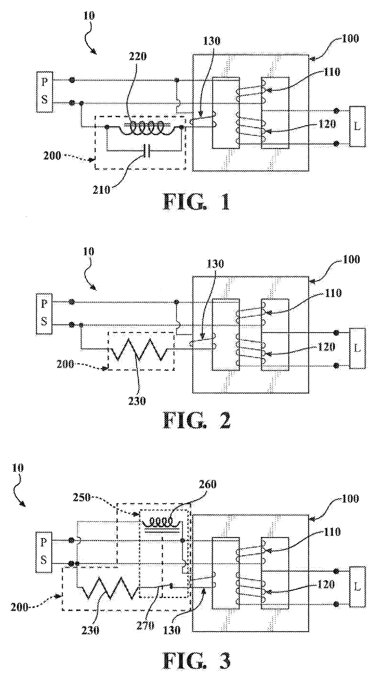
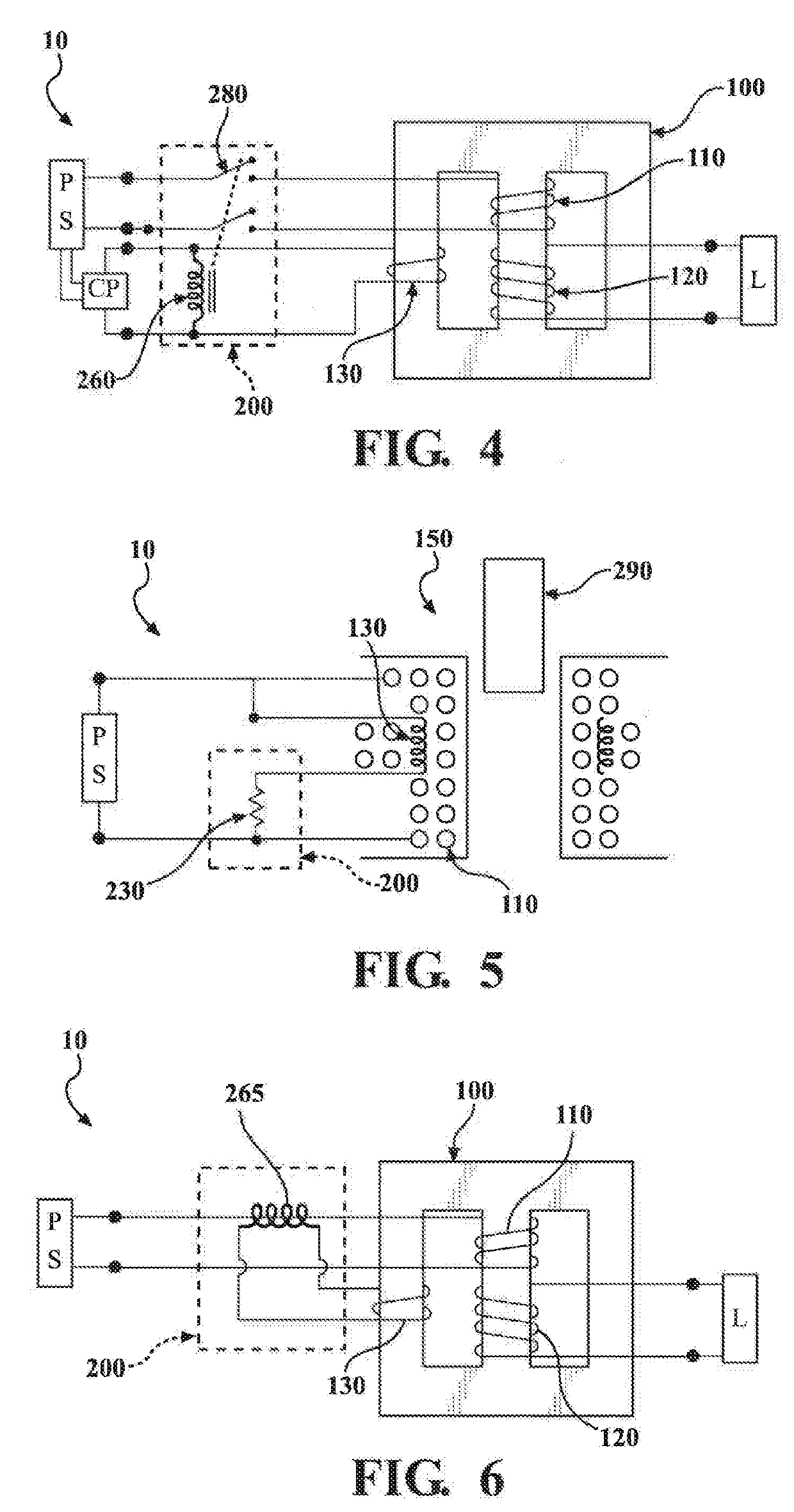
[0026]This invention relates to an inrush current suppression technique for suppressing the inrush current which occurs when a power supply is input to a device such as a transformer. FIG. 1 is a schematic diagram of a shell-type...


PUM

PropertyMeasurementUnit
voltage ratingaaaaaaaaaa
electrical energyaaaaaaaaaa
electrical poweraaaaaaaaaa

Abstract

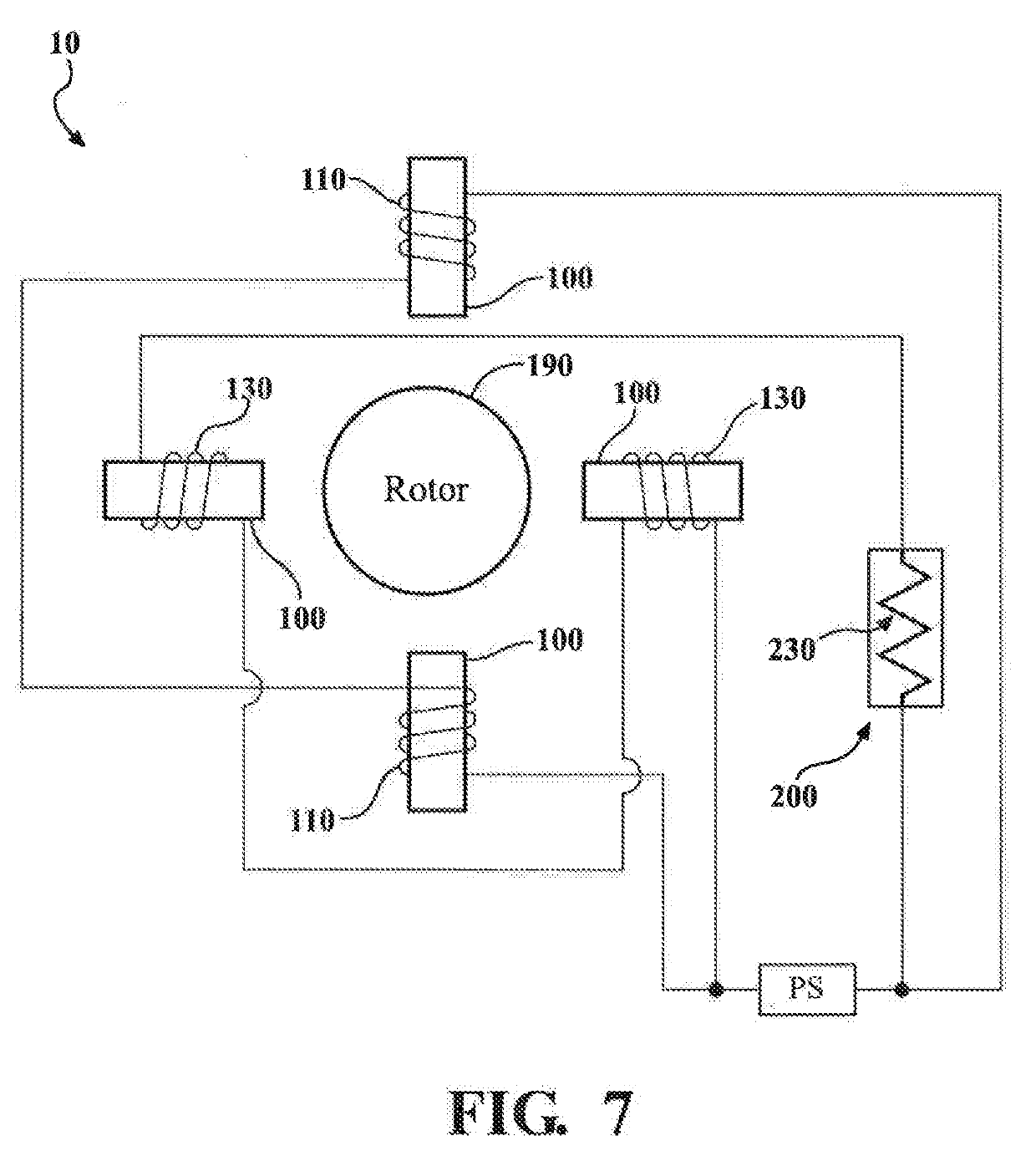
A pre-fluxing system and method to reduce inrush current for a winding used in a transformer, motor or a solenoid. The system has a primary winding and a tertiary winding connected with a power source for providing electrical energy to these windings. A pre-fluxing circuit is connected to the tertiary winding. The power source provides electrical energy to the tertiary winding via the pre-fluxing circuit, and the pre-fluxing circuit pre-magnetizes the tertiary winding when energized. The tertiary winding is configured to pre-magnetize the primary winding to reduce inrush current when the power source energizes the primary winding.

Description

REFERENCE TO RELATED APPLICATIONS[0001]This application claims priority to U.S. Provisional Patent Application Serial Nos. 62 / 635,778, filed Feb. 27, 2018; 62 / 643,559, filed Mar. 15, 2018; 62 / 657,376, filed Apr. 13, 2018; 62 / 683,380, filed Jun. 11, 2018; and 62 / 749,364, filed Oct. 23, 2018, the entire content of all of which is incorporated herein by reference.FIELD OF THE INVENTION[0002]The present invention relates generally to an inrush current suppression technique and, more particularly, to a circuit, method and system for pre-fluxing a winding used in a transformer, motor or a solenoid valve to reduce inrush current.BACKGROUND OF THE INVENTION[0003]When energizing an electromagnetic coil based device, such as a transformer, motor or solenoid, in an electric power delivery system (such as an electric power generation, transmission, or distribution system, or the like), inrush currents may occur which can be as large as ten times the device's nominal current and can last for up ...

Claims


Application Information

Patent Timeline
Patent Type & Authority Applications(United States)
IPC IPC(8): H02H9/00H01F27/28H01H50/16H02H7/04
CPCH02H9/002H02H7/04H01H50/16H01F27/28H01H50/54
Inventor MEISEL, DAVID
Owner MEISEL DAVID
Why Eureka
Eureka Blog
Learn More