Distal tibial plating system
- Summary
- Abstract
- Description
- Claims
- Application Information
AI Technical Summary
Benefits of technology
Problems solved by technology
Method used
Image
Examples
first embodiment
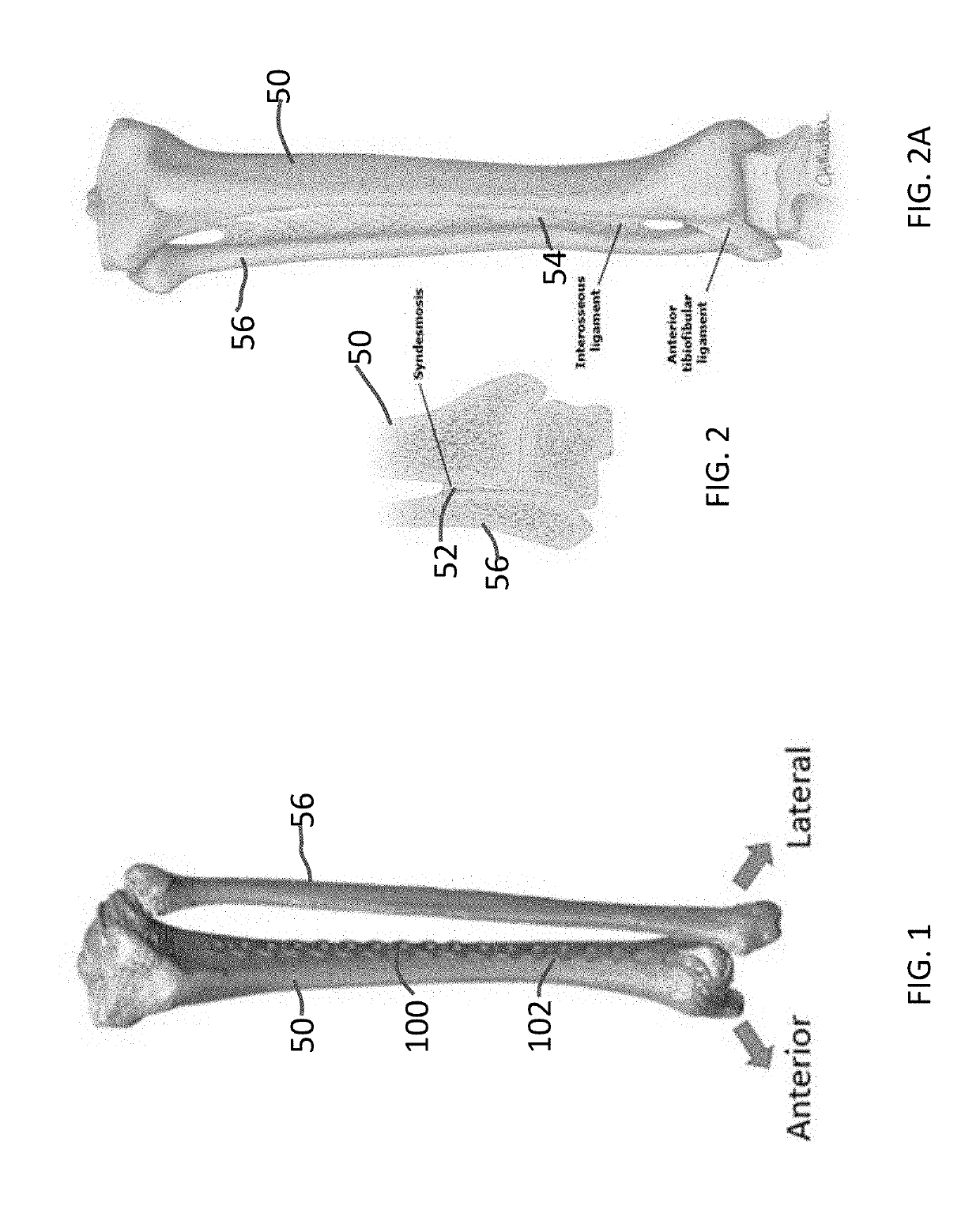
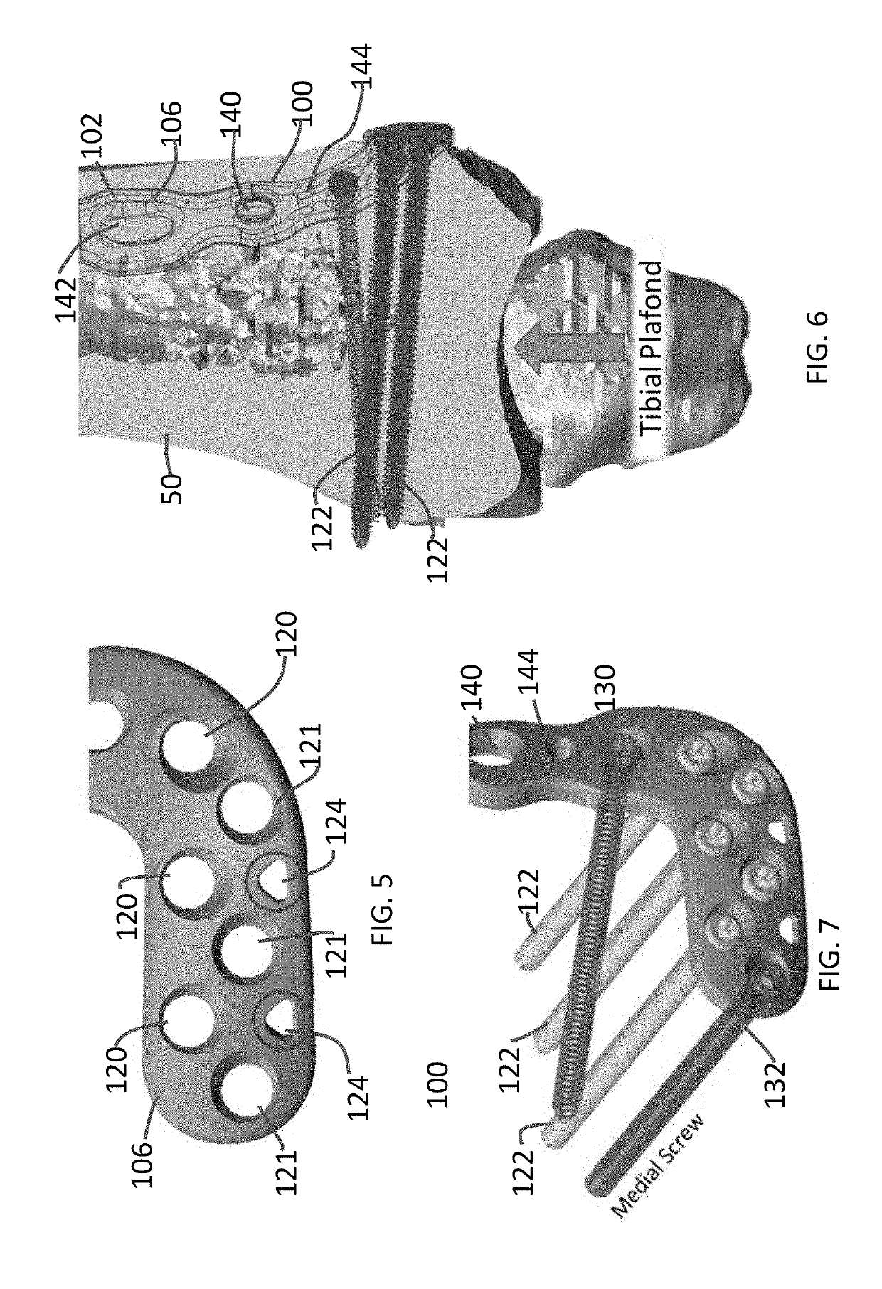
[0068]FIGS. 1 and 3-15 disclose an anterolateral bone plate system 100 (“system 100”) in accordance with a Referring to FIGS. 1-2A, system 100 is attached to a tibia 50 and is contoured to fit along the anterior-lateral portion of the tibia 50 along the syndesmosis 52 and the interosseous ligament 54 and extend onto the anterior portion of the tibia 50 (FIG. 1). The syndesmosis is a ligamentous attachment between the fibula 56 and the tibia 50 (See FIGS. 2 and 2A). An anterolateral bone plate 102 of system 100 is specific to the left and right tibia.
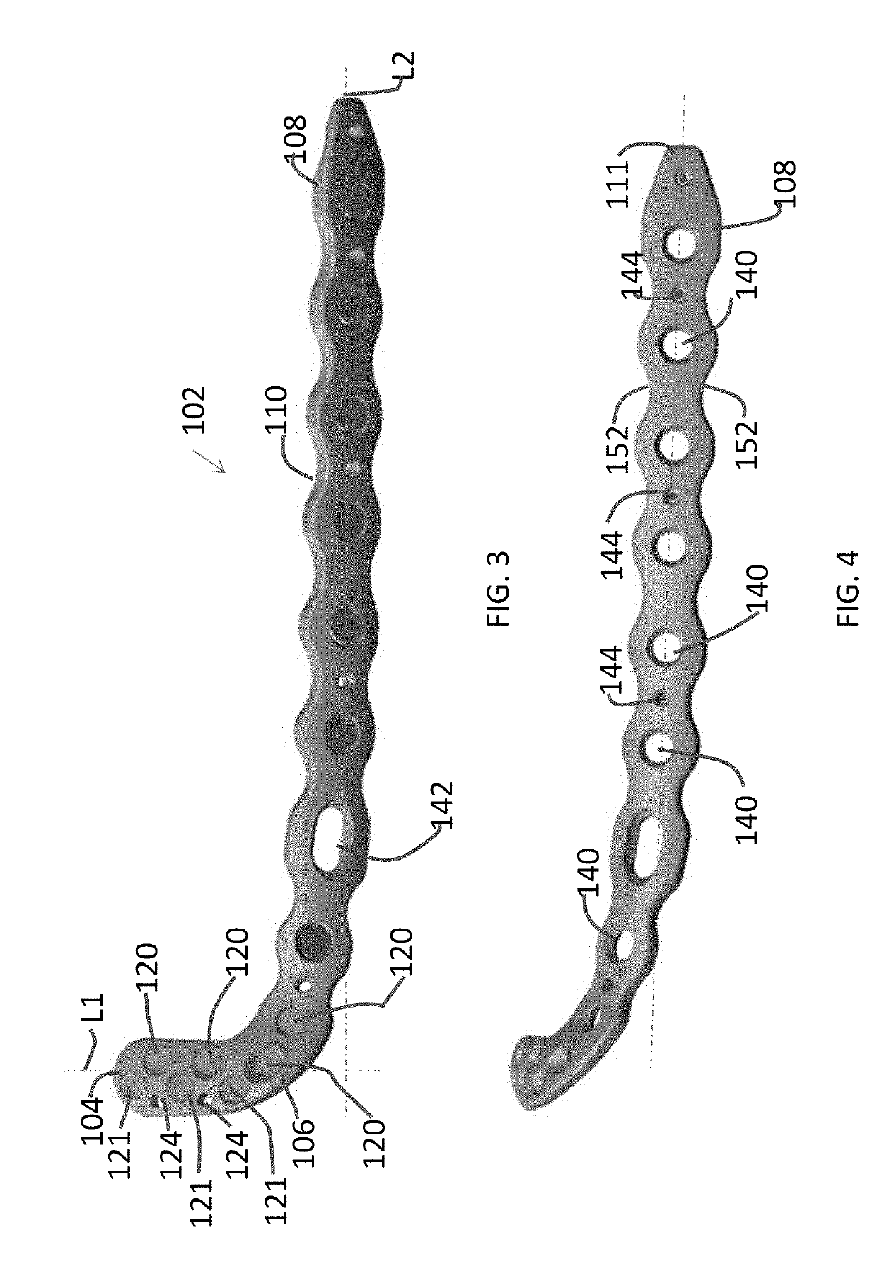
[0069]Referring to FIGS. 3 and 4, the bone plate 102 has a plurality of through holes formed therein for receiving fasteners, wherein at least some of the fasteners received therein are locking fasteners. The bone plate 102 comprises an inferior end 104 having a base portion 106 and a superior end 108 having a shaft portion 110. The bone plate 102 is multi-planar, with the shaft portion 110 extending generally in a singular plane, while...
second embodiment
[0082]FIGS. 16-26 disclose a bone plate system 200 (“system 200”) in accordance with a System 200 includes a medial bone plate 202 that is contoured to fit along the medial portion of the tibia 50 (FIGS. 16 and 19). Bone plate 202 of system 200 is specific to the left and right tibia. The medial distal tibia 50 is an area of little soft tissue coverage and is by far one of the most challenging areas to treat pilon fractures from. The thickness of the plate 202 is minimal to reduce soft tissue irritation and failure.
[0083]Referring to FIG. 17 the bone plate 202 has a plurality of through holes formed therein for receiving fasteners, wherein at least some of the fasteners received therein are locking fasteners. The bone plate 202 comprises an inferior end 204 having a base portion 206 and a superior end 208 having a shaft portion 210. The bone plate 202 has a curvature as shown in FIG. 19, to accommodate the curvature of the inferior end of the tibia 50.
[0084]The body 202 extends alo...
third embodiment
[0098]FIGS. 27-33 disclose a bone plate system 300 (“system 300”) in accordance with a System 300 includes a posterior bone plate 302 that is contoured to fit along the posterior portion of the tibia 50 (FIGS. 27 and 28). Bone plate 302 of system 300 is interchangeable for left-leg and right-leg tibias 50.
[0099]Referring to FIGS. 29 and 30, the bone plate 302 has a plurality of through holes formed therein for receiving fasteners, wherein at least some of the fasteners received therein are locking fasteners. The bone plate 302 comprises an inferior end 304 having a base portion 306 and a superior end 308 having a shaft portion 310. As shown in FIG. 30, the bone plate 302 is multi-planar, with the most superior end of the shaft portion 310 extending generally in a singular plane, while the most inferior end of the shaft portion 310 is curved away from the plane and extends across more than one plane. The curvature of the most inferior end of the shaft portion 310 relative to the mos...
PUM
 Abstract
Description
Claims
Application Information
 - R&D Engineer
- R&D Manager
- IP Professional
- Industry Leading Data Capabilities
- Powerful AI technology
- Patent DNA Extraction
Browse by: Latest US Patents, China's latest patents, Technical Efficacy Thesaurus, Application Domain, Technology Topic, Popular Technical Reports.
© 2024 PatSnap. All rights reserved.Legal|Privacy policy|Modern Slavery Act Transparency Statement|Sitemap|About US| Contact US: help@patsnap.com


