
Modular Jig and Fixture Systems and Methods

a technology applied in the field of modular jigs and fixtures, can solve the problems of less efficient design, bulky and more expensive, and achieve the effect of easy customizing and making jigs

Active Publication Date: 2019-09-05
DUGINSKE MARK A
View PDF15 Cites 9 Cited by
  • Summary
  • Abstract
  • Description
  • Claims
  • Application Information

AI Technical Summary

Benefits of technology

The patent text describes different types of jigs and fixtures used to align, guide, and hold workpieces on woodworking machinery during woodworking operations. The patent also describes methods to make, modify, and use these jigs and fixtures. The technical effects of this patent include improved alignment accuracy, easier customization, and efficient use of space on woodworking machinery.

Problems solved by technology

However, in that attempt, the construction and operation of the clamp mechanism required increased clearance and caused interference with the support surface upon which the pocket hole jig was placed or mounted.
In a further attempt to address these interference issues, the base thickness was increased to provide additional clearance for the clamping mechanism, which ultimately resulted in a less efficient design that was bulk and more costly.

Method used


Image

  • Modular Jig and Fixture Systems and Methods
  • Modular Jig and Fixture Systems and Methods
  • Modular Jig and Fixture Systems and Methods

Examples


Embodiment Construction

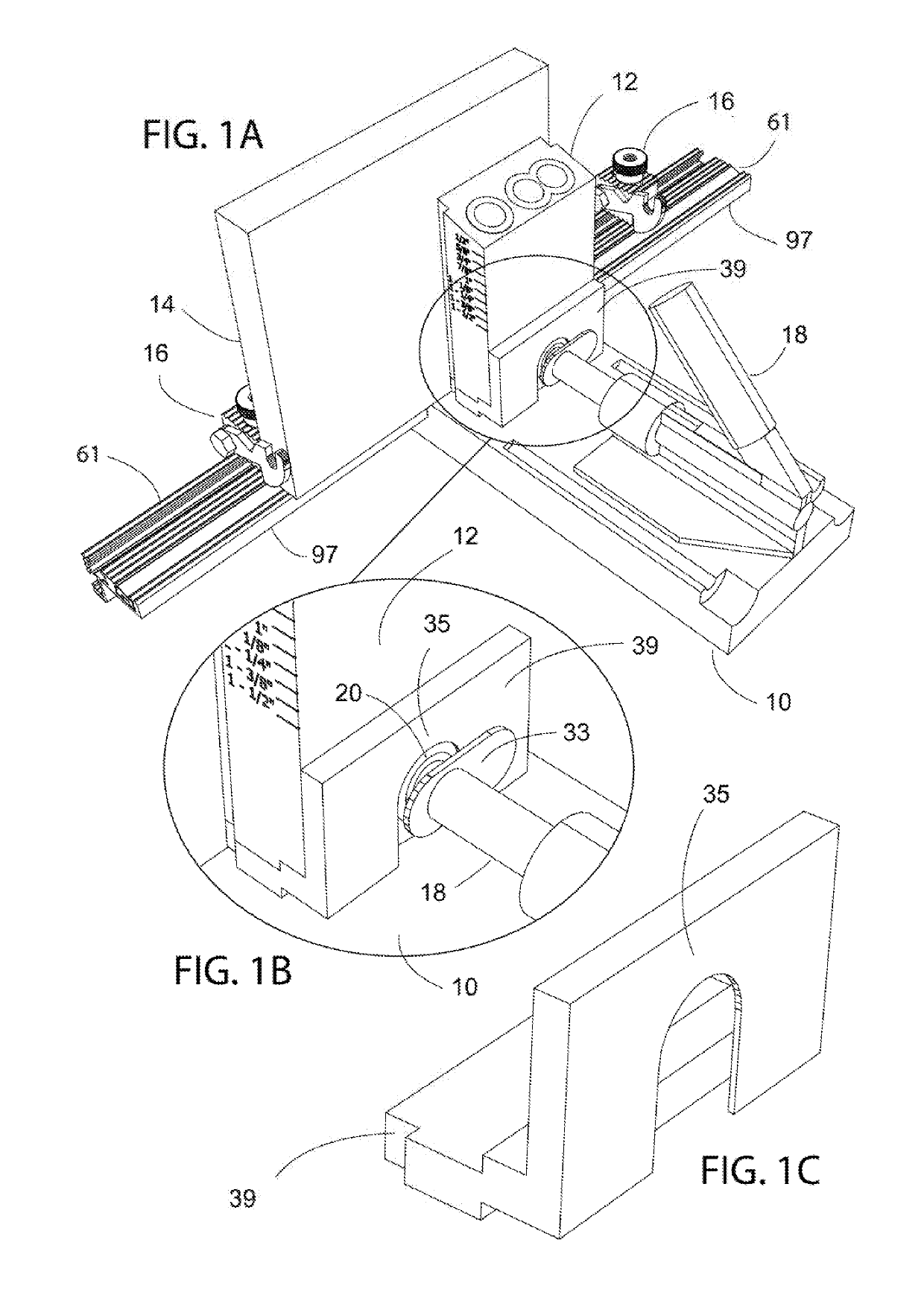
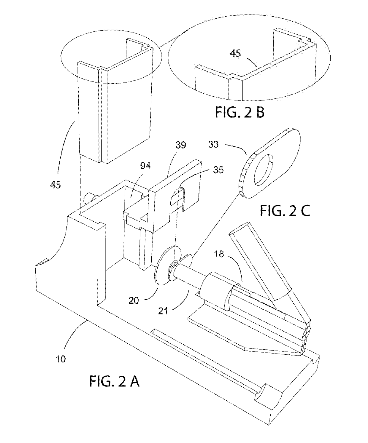
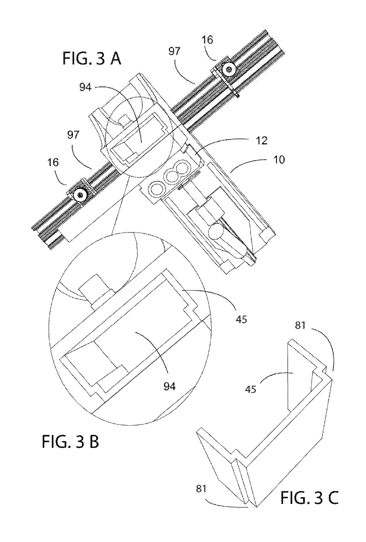
[0205]Embodiments of the invention are illustrated in extensive detail in the accompanying FIGS. 1-65, as set forth above in the description of FIGS. 1-65, and as elaborated below in the detailed description. As shown in FIGS. 1-65, jigs and fixtures for aligning, guiding, and / or holding a workpiece on woodworking machinery during a woodworking operation are described, as well as methods of making, modifying, and using jigs and fixtures. For instance, a modular track and flip stop with a corrugated surface on the top and face of the track as well as a mating corrugated pattern on the bottom and top of the flip stop base are also described. Moreover, a flip stop base that may be created from two identical mating parts that allows the top and bottom to be separated so the bolt can be moved without the need to disassemble the bolt and flip arm assembly is further disclosed. In addition, a modular miter gauge head and bar system for easily making custom jigs, fixtures, and sleds are dis...


PUM

PropertyMeasurementUnit
Structureaaaaaaaaaa

Abstract

Jigs and fixtures for aligning, guiding, and / or holding a workpiece on woodworking machinery during a woodworking operation are described, as well as methods of making, modifying, and using jigs and fixtures.

Description

CROSS-REFERENCE TO RELATED APPLICATIONS[0001]This application claims priority under 35 U.S.C. § 119 to U.S. Provisional Patent Application No. 62 / 637,456 filed on Mar. 2, 2018, entitled “Modular Jig and Fixture Systems and Methods,” which is hereby incorporated by reference as if fully set forth herein.STATEMENT CONCERNING FEDERALLY SPONSORED RESEARCH OR DEVELOPMENT[0002]Not applicable.FIELD OF THE INVENTION[0003]This invention relates to jigs and fixtures for aligning, guiding, and / or holding a workpiece on woodworking machinery during a woodworking operation.BACKGROUND OF THE INVENTION[0004]Woodworking often employs a multitude of tools and machines to accomplish a variety of intricate operations. Challenges abound in addressing the ever-present desire to enhance efficient woodworking tools, machines, and methods. For instance, attempts have been made to improve the use of pocket hole jigs by enhancing access to the drill guide, such as by providing activation of the clamp from th...

Claims


Application Information

Patent Timeline
IPC IPC(8): B23B47/28
CPCB23B47/287B23B2247/10B23B2260/088B23B2260/004B23B2247/12B27B27/08B27B27/10B23B47/288B23Q3/06B25B5/006
Inventor DUGINSKE, MARK A.
Owner DUGINSKE MARK A
Learn More