Electromagnetic clutch and compressor provided with same

a technology of electromagnetic clutch and compressor, which is applied in the direction of non-mechanical actuated clutches, clutches, piston pumps, etc., can solve the problems of abnormal temperature of the contact portion, prevent the malfunction of the thermal fuse, and interrupt the electric power supply to the electromagnetic coil more quickly

Active Publication Date: 2019-09-05
SANDEN CORP
View PDF0 Cites 0 Cited by
  • Summary
  • Abstract
  • Description
  • Claims
  • Application Information

AI Technical Summary

Benefits of technology

[0008]In the electromagnetic clutch according to the above aspect, the thermally actuated switch turns ON / OFF the electric power supply to the electromagnetic coil such that the temperature in the vicinity of the thermal fuse does not exceed the operational temperature due to self-heating of the electromagnetic coil itself. Thus, it is possible to prevent malfunction of the thermal fuse due to self-heating of the electromagnetic coil itself by the thermally actuated switch during normal operation in which the rotating shaft is not locked. In this way, it is possible to prevent malfunction of the thermal fuse by the thermally actuated switch, so that it is possible to set the operational temperature of the thermal fuse without taking into consideration the maximum attainable temperature due to the self-heating of the electromagnetic coil itself under the severest conditions imaginable. Accordingly, it is unnecessary to set the operational temperature of the thermal fuse at a level higher than necessary. As a result, it is possible to set the operational temperature of the thermal fuse lower than the conventional set value (e.g., 180° C.), and when the rotating shaft is locked, it is possible to interrupt the electric power supply to the electromagnetic coil more quickly than in the prior art. Thus, even in a low temperature atmosphere, it is possible to shorten the electric power supply time in the locked state, making it possible to more reliably protect components such as the bearing of the rotor and the driving belt or the drive source such as the engine.
[0009]In this way, there is provided an electromagnetic clutch capable of shortening, even in a low temperature atmosphere, the requisite time from when the rotating shaft is locked to when the thermal fuse is operated (fuse reaction time) while preventing or suppressing malfunction of the thermal fuse due to self-heating of the electromagnetic coil.

Problems solved by technology

In an electromagnetic clutch of this type, when the rotating shaft of the compressor is locked for some reason or other, slippage is generated in the contact portion between the armature and the rotor, so that the temperature of this contact portion is increased to an abnormal degree due to frictional heat.

Method used


Image

  • Electromagnetic clutch and compressor provided with same
  • Electromagnetic clutch and compressor provided with same
  • Electromagnetic clutch and compressor provided with same

Examples


first embodiment

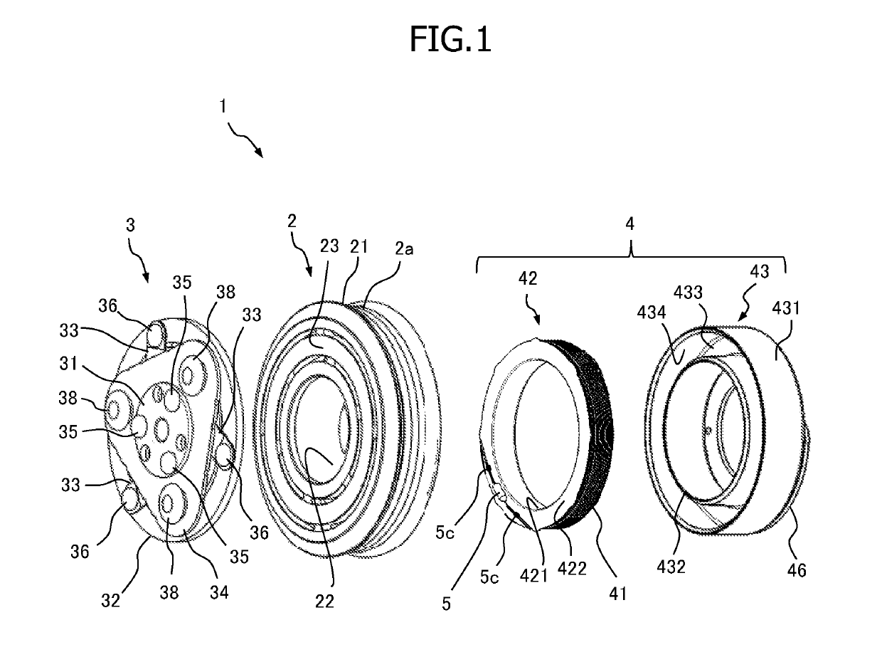
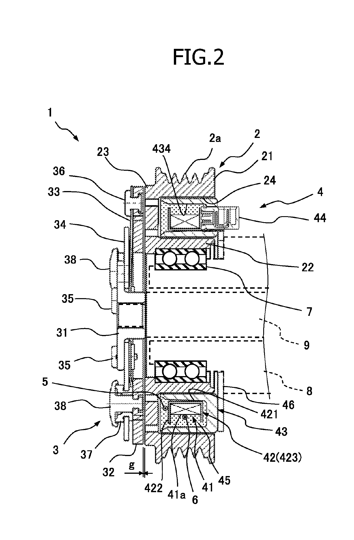
[0018]FIGS. 1 and 2 illustrate the structure of an electromagnetic clutch 1 according to the present invention. FIG. 1 is an exploded perspective view of the electromagnetic clutch 1, and FIG. 2 is a sectional view of the electromagnetic clutch 1.

[0019]The electromagnetic clutch 1 of the present embodiment is incorporated into a compressor constituting, for example, a vehicle air conditioner, and intermittently transmits the power of a vehicle engine and a motor as a drive source to a compressor as a driven apparatus. That is, the electromagnetic clutch 1 effects switching between the transmission of power from the engine or the motor to the compressor and the interruption thereof. The compressor according to the present invention is equipped, for example with the electromagnetic clutch 1, and embodiments thereof will be described below. The compressor is operated by transmitting power from the engine or the motor, and stops its operation when the transmission of power from the engi...

second embodiment

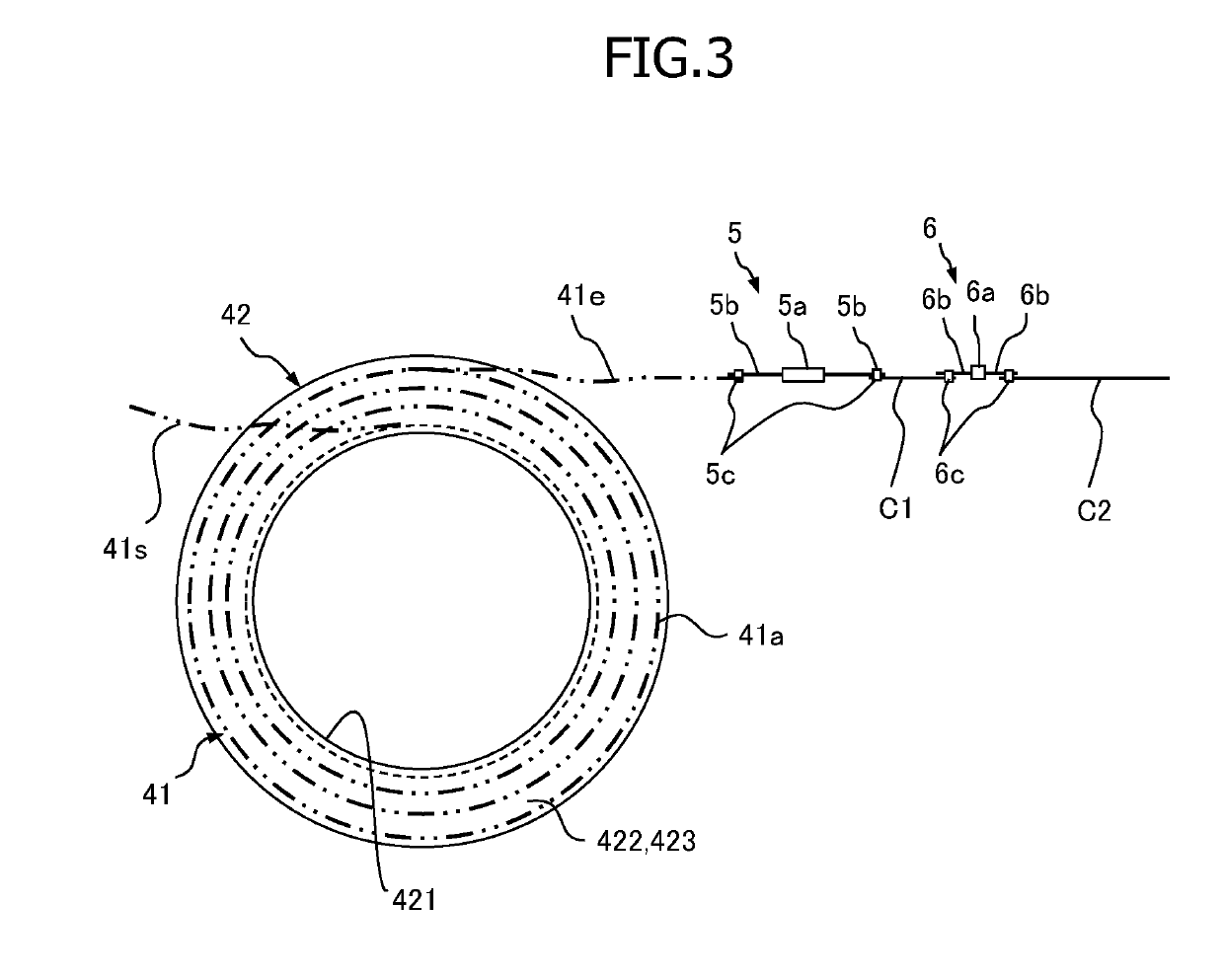
[0050]In a case in which the rotating shaft 9 is locked, serious failure has been generated in the compressor, and thus, after the locking, in order that the electric power supply may not be restored, it is necessary to reliably operate the thermal fuse 5 to turn off the electric power supply to the electromagnetic coil 41, forcibly releasing the connection between the rotor 2 and the armature 3. For example, even if the switching temperature Ts is set to be lower than the operational temperature Tf, in a case in which the temperature difference ΔTfs between the operational temperature Tf and the switching temperature Ts is greater than the temperature difference ΔTos (that is, the overshoot amount) between the predetermined maximum temperature To in the overshoot phenomenon and the switching temperature Ts (ΔTfs>ΔTos), the thermal fuse vicinity temperature T1 is allowed to begin to be lowered before reaching the operational temperature Tf. Thus, before the thermal fuse 5 begins to ...


PUM


Abstract

Provided is an electromagnetic clutch capable of shortening, even in a low temperature atmosphere, the fuse reaction time from when a rotating shaft is locked, while preventing or suppressing malfunction of the thermal fuse. An electromagnetic clutch 1 is equipped with a rotor 2, an armature 3, an electromagnetic coil unit 4, a thermal fuse 5, and a thermally actuated switch 6. The thermally actuated switch 6 is connected in series to an electromagnetic coil 41 of the electromagnetic coil unit 4 along with the thermal fuse 5. When a temperature of the thermally actuated switch 6 exceeds a switching temperature (predetermined temperature) Ts, the thermally actuated switch 6 is displaced in an electric power supply OFF direction, and thereafter, it is displaced in an electric power supply ON direction due to a reduction in temperature. The thermally actuated switch 6 turns ON / OFF the electric power supply to the electromagnetic coil 41 such that the thermal fuse vicinity temperature T1 does not exceed the operational temperature Tf of the thermal fuse 5 due to self-heating of the electromagnetic coil 41 itself generated by the electric power supplied to the electromagnetic coil 41, thereby preventing malfunction of the thermal fuse 5 due to self-heating of the electromagnetic coil 41.

Description

TECHNICAL FIELD[0001]The present invention relates to an electromagnetic clutch and, in particular, relates to an electromagnetic clutch intermittently transmitting power of a vehicle engine or a motor to a compressor of a vehicle air conditioner, or the like.BACKGROUND ART[0002]As an example of an electromagnetic clutch of this type, there is known the electromagnetic clutch disclosed in Patent Document 1. The electromagnetic clutch disclosed in Patent Document 1 is equipped with a rotor rotated by the power of a drive source, an armature arranged opposite this rotor and connected to the rotating shaft of a compressor, an electromagnetic coil unit having a bobbin around which an electromagnetic coil is wound and causing the rotor and the armature to be magnetically attracted to each other by electric power supplied to this electromagnetic coil unit, and a thermal fuse that is blown when a temperature thereof exceeds a predetermined operational temperature to interrupt the electric ...

Claims


Application Information

Patent Timeline
Patent Type & Authority Applications(United States)
IPC IPC(8): F16D27/112F16D27/14
CPCF16D27/112F16D2027/002F16D27/14F04B35/00F16D27/10
Inventor SAKAMOTO, YUKI
Owner SANDEN CORP
Why Eureka
Try Eureka