Reversible system for dissipating thermal power generated in a gas-turbine engine

Active Publication Date: 2019-09-12
SAFRAN
View PDF0 Cites 0 Cited by
  • Summary
  • Abstract
  • Description
  • Claims
  • Application Information

AI Technical Summary

Benefits of technology

[0009]An object of the present invention is thus to provi

Problems solved by technology

Unfortunately, such FCOC heat exchangers are no longer sufficient to absorb all of the heat dissipated by the engine, in particular because the temperature to which the fuel can be raised is limited by safety constraints.
In order to exchange large amounts of heat, such a heat exchanger needs to present a large area, and thus also presents weight and size that are large.
Such heat exchangers are relatively heavy and they suffer from the disadvantage of disturbing the air stream, and thus of penalizing the overall efficiency of the turbine engine (leading to an increase in its

Method used


Image

  • Reversible system for dissipating thermal power generated in a gas-turbine engine
  • Reversible system for dissipating thermal power generated in a gas-turbine engine

Examples


Embodiment Construction

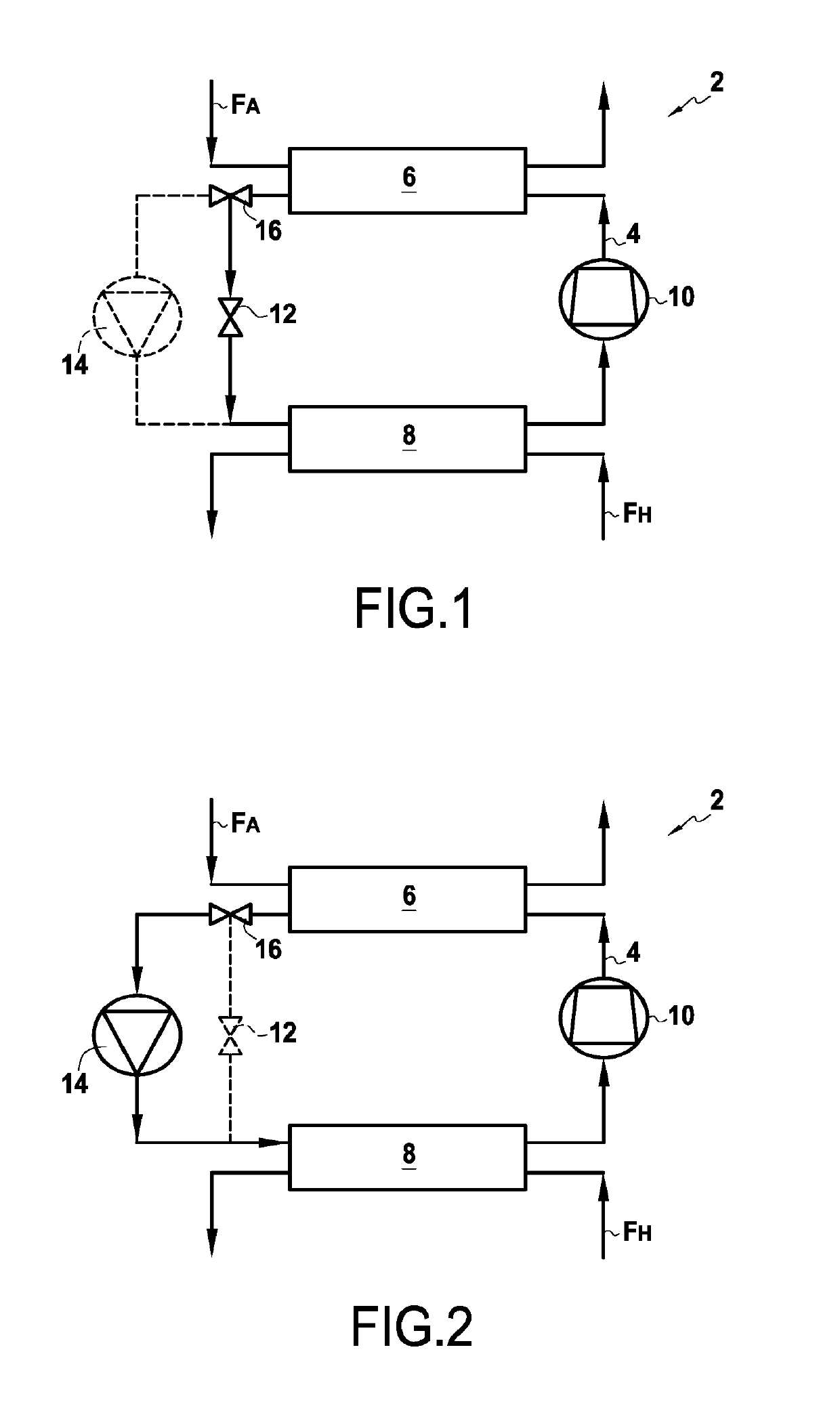
[0026]The invention applies to dissipating any type of heat power generated in a gas turbine engine and that needs to be discharged.

[0027]The example described below relates more particularly to dissipating the heat power generated by heating the oil in an oil circuit of a turbine engine. Nevertheless, the system of the invention could equally well apply to dissipating heat power coming from the heating of various electrical components of a gas turbine engine, e.g. such as batteries or electrical power generators.

[0028]In known manner, the oil circuit of a turbine engine includes various pieces of equipment that use the cooling and / or lubricating oil, such as bearings (in particular for the turbine and compressor shafts), gearboxes (such as the accessory gearbox), electricity generators, etc.

[0029]The oil circuit also includes return pumps for recirculating the oil from the equipment to an oil tank, feed pumps, one or more filters, and one or more oil / fuel heat exchangers (FCOC heat...


PUM


Abstract

A reversible system for dissipating heat power generated in a gas turbine engine, the system including a condenser-forming first heat exchanger, an evaporator-forming second heat exchanger, a scroll compressor suitable for operating as a compressor when the temperature of the cold source is higher than a predefined threshold temperature and as a turbine when the temperature of the cold source is lower than the threshold temperature, an expander and a pump arranged in parallel, and a control valve arranged upstream from the expander and the pump and suitable for directing the refrigerant fluid to the expander when the temperature of the cold source is higher than the threshold temperature and to the pump when the temperature of the cold source is lower than the threshold temperature.

Description

BACKGROUND OF THE INVENTION[0001]The present invention relates to the general field of dissipating heat powers generated in a gas turbine engine. The invention relates in particular to cooling the oil circuit of an airplane turbine engine.[0002]In known manner, a gas turbine engine includes an oil circuit that is used to lubricate and / or cool various pieces of equipment in the engine, such as bearings, gearboxes, etc. The engine also has a fuel circuit that feeds injectors mounted in the combustion chamber of the engine.[0003]The oil flowing in the oil circuit of the engine is typically cooled by heat exchangers of the fuel / oil type, known as fuel cooled oil coolers (FCOCs) or of the air / oil type known as air cooled oil coolers (ACOCs).[0004]FCOC heat exchangers perform two functions, both heating the fuel before it is injected into the combustion chamber, and also cooling the oil that is heated by the heat dissipated by the engine. Unfortunately, such FCOC heat exchangers are no lo...

Claims


Application Information

Patent Timeline
IPC IPC(8): F01K25/02F02C7/16F02C7/14F02C7/141F01K15/00
CPCF05D2260/213F01K25/02F02C7/14F05D2260/98F02C7/16F02C7/141F01K15/00F02C1/10F02C7/18Y02T50/60
Inventor MAALOUF, SAMER
Owner SAFRAN
Why Eureka
Try Eureka