Systems and methods of increasing pupil size in a display system

a display system and pupil technology, applied in the field of systems and methods of increasing the pupil size in the display system, can solve the problems of increasing power consumption, reducing image quality, and increasing cos

Active Publication Date: 2019-09-12
MICROSOFT TECH LICENSING LLC
View PDF0 Cites 9 Cited by
  • Summary
  • Abstract
  • Description
  • Claims
  • Application Information

AI Technical Summary

Problems solved by technology

Due to high frequency of the mirror movement, increasing the size of the mirror may degrade the image quality (due to di

Method used


Image

  • Systems and methods of increasing pupil size in a display system
  • Systems and methods of increasing pupil size in a display system
  • Systems and methods of increasing pupil size in a display system

Examples


Embodiment Construction

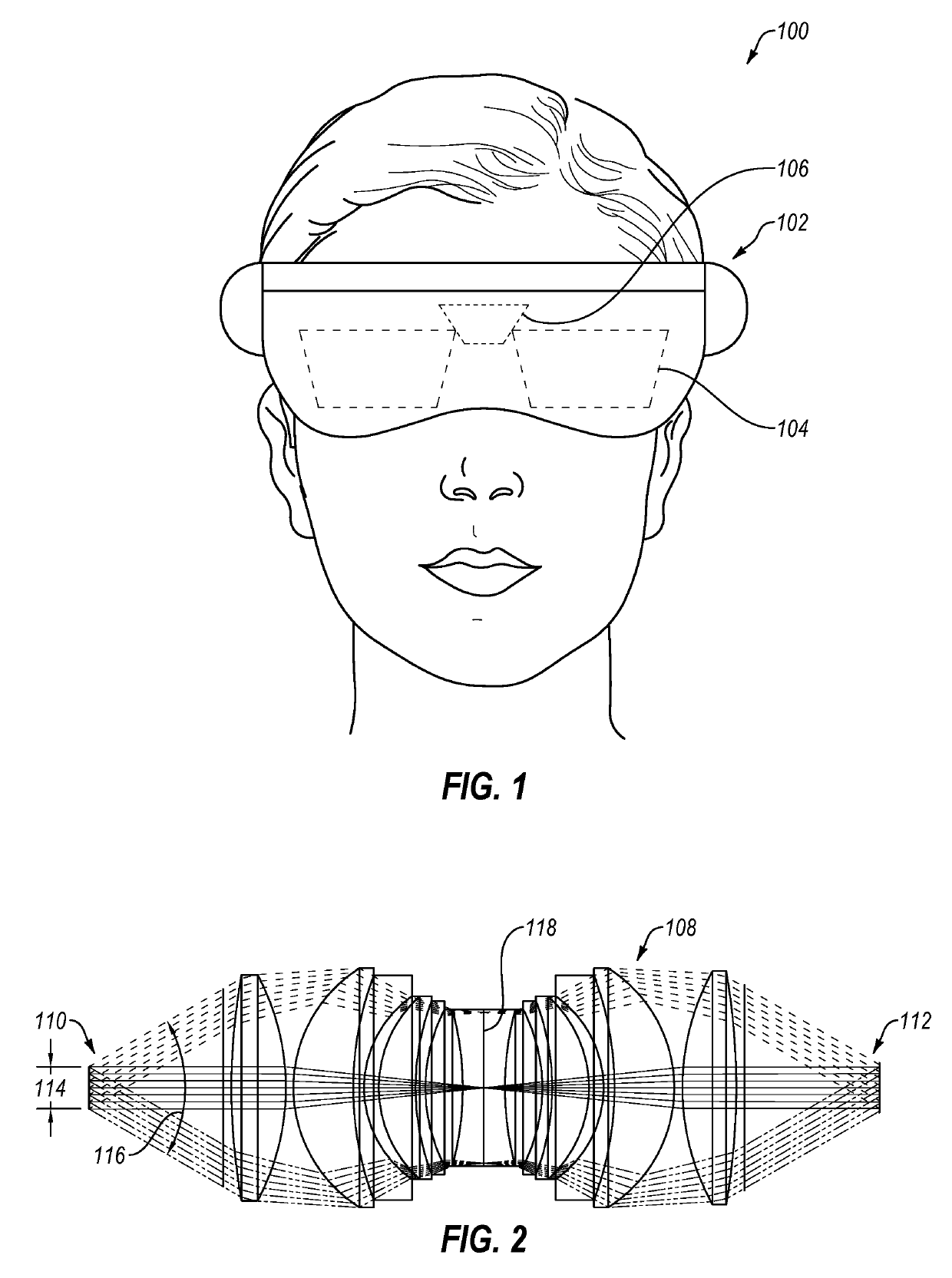
[0023]This disclosure generally relates to devices, systems, and methods for providing visual information to a user. More specifically, the present disclosure relates to delivering light to a waveguide providing visual information to a user. In some embodiments, visual information may be provided to a user by a near-eye display. A near-eye display may be any display that is positioned near a user's eye, either to supplement a user's view of their surroundings, such as augmented or mixed reality devices, or to replace the user's view of their surroundings, such as virtual reality devices. In some embodiments, an augmented reality or mixed reality device may be a head-mounted display (HMD) that presents visual information to a user overlaid on the user's view of their surroundings. For example, the visual information from the HMD may be combined with ambient or environment light to overlay visual information, such as text or images, on a user's surroundings.

[0024]In some embodiments, ...


PUM


Abstract

A display system for presenting visual information to a user includes a fast scan mirror, a slow scan mirror, and anamorphic relay optics positioned optically between the fast scan mirror and slow scan mirror. The fast scan mirror has a fast scan arc in a scan direction of a display light provided by a light source. The slow scan mirror has a slow scan arc in a cross-scan direction of the display light that is perpendicular to the scan direction. The anamorphic relay optics are configured to magnify the display light in the cross-scan direction.

Description

CROSS-REFERENCE TO RELATED APPLICATIONS[0001]N / ABACKGROUND OF THE DISCLOSURE[0002]Augmented reality (AR) and mixed reality (MR) display systems allow a user to experience visual information presented from a computer simultaneously with ambient light from the user's surroundings. One method for allowing a user to view their surroundings while receiving additional visual information introduced in their field of view is a waveguide. A waveguide allows ambient light to reach a user's eyes, while also allowing light from a display device to be directed to the user's field of view and combined with the ambient light.[0003]Visual information is displayed on the waveguide by directing display light through the waveguide. The display light may be generated by a light source optically connected to the waveguide through one or more optical elements. The field of view of the visual information provided through the waveguide is related to the pupil size of the light in-coupled to the waveguide. ...

Claims


Application Information

Patent Timeline
IPC IPC(8): G02B26/08G06T19/00G02F1/1335
CPCG02B27/0172G02B2027/0138G06T19/006G02B2027/0178G06F3/011G06F3/04815G02B26/0833G02B2027/014G02F1/1335G02B13/08G02B26/101G02B2027/0123
Inventor CHEN, FEIMILLER, JOSHUA OWEN
Owner MICROSOFT TECH LICENSING LLC
Why Eureka
Try Eureka