
Method and apparatus for evaluating damage to magnetic linear body

Active Publication Date: 2019-09-19
TOKYO ROPE MFG
View PDF0 Cites 2 Cited by
  • Summary
  • Abstract
  • Description
  • Claims
  • Application Information

AI Technical Summary

Benefits of technology

The patent aims to reduce the loss of magnetomotive force in a magnetizer that is used to magnetize a magnetic linear body embedded in concrete. The invention proposes the use of a plurality of Hall devices that are oriented in a way that responds to magnetic flux in the radial direction of the magnetic linear body. This allows for more accurate detection of magnetic leakage flux. In summary, the technical effect of the patent is to enhance the efficiency of magnetic linear body magnetization.

Problems solved by technology

Damage includes abrasion, corrosion, severance and the like.

Method used


Image

  • Method and apparatus for evaluating damage to magnetic linear body
  • Method and apparatus for evaluating damage to magnetic linear body
  • Method and apparatus for evaluating damage to magnetic linear body

Examples


Embodiment Construction

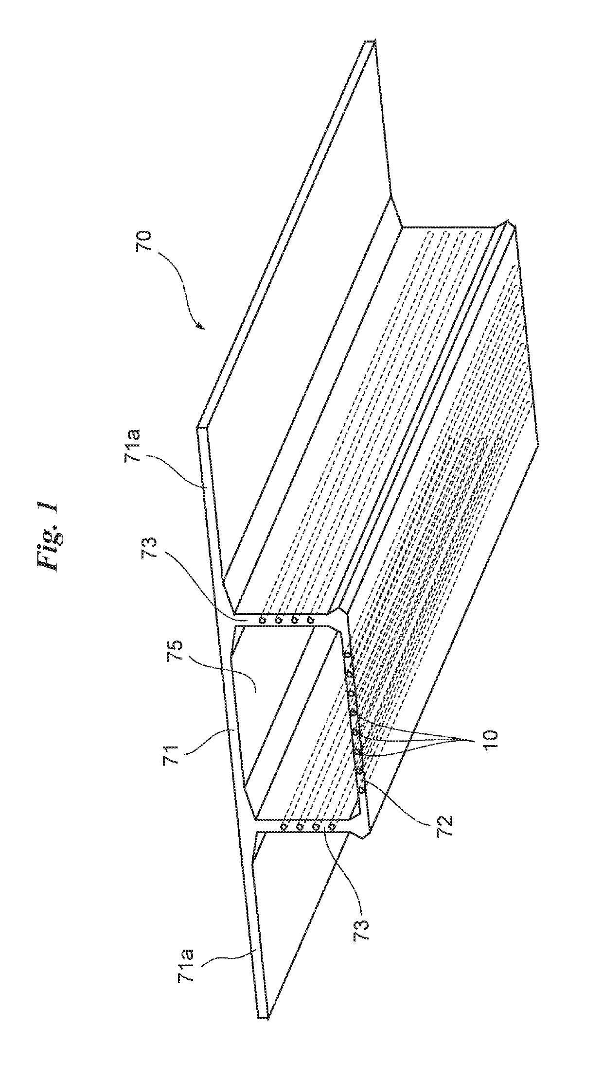
[0030]FIG. 1 is a perspective view in which a box girder constituting a concrete box-girder bridge is seen from below.

[0031]The concrete box-girder bridge is fabricated by joining multiple concrete girders 70, made of concrete, along the axial direction of the bridge. The girder 70 is composed of an upper flange 71, a lower flange 72 provided below the upper flange 71 substantially in parallel with the upper flange 71 and spaced away therefrom, and webs 73 connecting respectively each of both side portions of the upper flange 71 and lower flange 72. A space 75 extending along the axial direction of the bridge and enclosed by the upper flange 71, lower flange 72 and webs 73 on both sides is large enough to allow entry of a person so that the concrete box-girder bridge (girder 70) can be inspected from within the space 75. Both sides of the upper flange 71 extend outward sideways from the respective sides, the width of the concrete box-girder bridge being decided by the upper flange 7...


PUM


Abstract

A damage evaluation apparatus, to evaluate damage to a tendon embedded in concrete. The apparatus includes a magnetizer for generating magnetic force, and a detector for detecting change in magnetism produced from a damaged area of the tendon when magnetized. The magnetizer includes a excitation coil; an iron core passing through a center hole of the excitation coil; a pair of columnar yokes connected to respective ends of the iron core and extending toward the concrete; and a pair of plate-shaped yokes connected to the pair of columnar yokes at a distal end thereof for forming magnetic poles having spread along the surface of the concrete. By passing an electric current through the excitation coil, a magnetic circuit is formed by the yoke shaft, the pair of columnar yokes, the pair of plate-shaped yokes, and the tendon over a range thereof situated between the pair of plate-shaped yokes.

Description

CROSS REFERENCE TO RELATED APPLICATIONS[0001]This application is a Continuation Application of PCT International Application No. PCT / JP2016 / 085704 filed on Dec. 1, 2016, the entire disclosure of the application being considered part of the disclosure of this application and hereby incorporated by reference.TECHNICAL FIELD[0002]The present invention relates to a method and apparatus for evaluating damage (state of deterioration) of a magnetic linear body, typically a magnetic linear body that is embedded in concrete. The linear body includes a cable, rope, strand, cord, wire, rod, pole, shaft or other object in a form extending continuously in one direction, and also includes not only twisted objects but also objects merely bundled together or alone. Further, size of diameter and cross-sectional shape of the body does not matter. The term “magnetic linear body” signifies a linear body produced from a magnetic material, typically a ferromagnetic material.BACKGROUND ART[0003]Japanese P...

Claims


Application Information

Patent Timeline
IPC IPC(8): G01N27/83G01N27/80G01R33/02G01N27/90G01V3/10G01R33/12G01N33/38
CPCG01N27/83G01N33/383G01R33/02G01N27/80G01R33/12G01V3/104G01N27/902G01N27/82G01R33/072G01R33/0094G01V3/081G01D5/145G01D11/245G01D3/022G01D5/202G01R33/093G01R33/09G01R31/2829G01R33/06
Inventor ITOI, HIROAKISHIIKI, SADANORISUGAHARA, MASAMICHIMORIYA, TOSHIYUKI
Owner TOKYO ROPE MFG
Features
  • Generate Ideas
  • Intellectual Property
  • Life Sciences
  • Materials
  • Tech Scout
  • Unparalleled Data Quality
  • Higher Quality Content
  • 60% Fewer Hallucinations
Learn More