Configuration of a battery of a vehicle having a plurality of drive units

a technology of drive unit and battery, which is applied in the direction of battery/cell propulsion, vehicle sub-unit features, electric devices, etc., can solve the problems of different energy consumption of n-phase electric machines, and achieve the reduction of storage capacity of respective energy modules, internal reduction of current strength, and the effect of reducing the storage capacity of the respective energy modul

Active Publication Date: 2019-09-19
DR ING H C F PORSCHE AG
View PDF3 Cites 11 Cited by
  • Summary
  • Abstract
  • Description
  • Claims
  • Application Information

AI Technical Summary

Benefits of technology

[0012]It is conceivable to arrange a respective N-phase electric machine on a respective axle in an electric vehicle. Furthermore, it is conceivable to arrange a respective N-phase electric machine on a respective wheel of the electric vehicle. Depending on the course of a journey and driving style, these N-phase electric machines have different energy consumption. The respective estimation of the load of the individual N-phase electric machines can be acquired from test drives or from journeys preceding a new journey, Adaptation of the estimation to a previously known route profile and / or a previously known driving style of an individual driver is conceivable. It is also conceivable for the respective N-phase electric machines to have different power data, for example in order to take into account a standard higher load of the drive on the rear axle. All these circumstances give rise to different discharging of a split battery, wherein generally uniform loading is to be preferred in order to avoid premature failure of part of the battery, which is used to a greater extent. As a result of the inventive execution of the method, a different loading and, under certain circumstances, a need to have to allow for an exchange of energy between the energy modules of individual groups as a result of different states of charge of the energy modules are advantageously reduced. In this context, different states of charge of the energy modules between individual groups, become all the smaller the better the success in estimating the energy consumption.
[0015]In one embodiment of the method according to aspects of the invention, some of the energy modules are assigned jointly to at least two N-phase electric machines. As a result, a transmission of energy can take place between these at least two N-phase electric machines. The better the success in estimating the respective energy consumption, the fewer energy modules which are connected to one another have to be made available for the purpose of the transmission of energy.
[0017]In a further embodiment of the method according to aspects of the invention, the respective energy modules in the group of the plurality of energy modules which is assigned to the respective N-phase electric machine are dimensioned in respect of a storage capacity. This requires energy modules with different storage capacity to be made available, which can be achieved, for example, by using energy cells with a different storage capacity. It is also conceivable to change the number of energy cells, which are connected in parallel per energy module. In this context, the terminal voltage per energy cell and therefore also the group terminal voltage value remain unchanged. However, an internal resistance of the respective energy module and therefore a current strength, which is made available, are also changed with the storage capacity. If, for example, the storage capacity of the respective energy module is reduced, the internal resistance of the respective energy module which becomes larger reduces the current strength which is applied by the respective energy module.

Problems solved by technology

Depending on the course of a journey and driving style, these N-phase electric machines have different energy consumption.

Method used


Image

  • Configuration of a battery of a vehicle having a plurality of drive units
  • Configuration of a battery of a vehicle having a plurality of drive units
  • Configuration of a battery of a vehicle having a plurality of drive units

Examples


Embodiment Construction

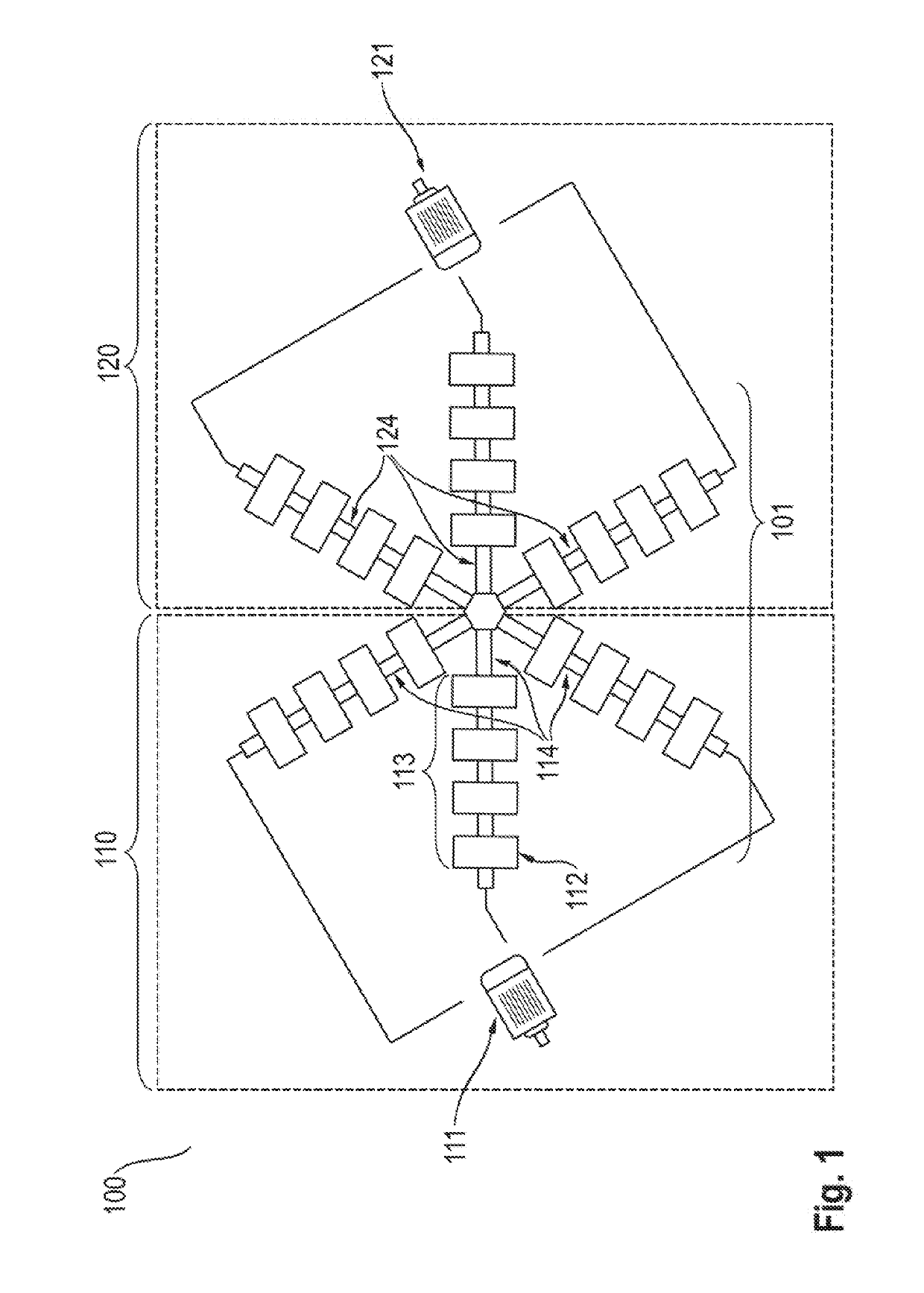
[0033]FIG. 1 shows a schematic illustration 100 according to the prior art of two drive systems 110 and 120 which are assigned to a respective axle of a motor vehicle. A three-phase electric motor 111 and a three-phase electric motor 121 are respectively arranged on a front axle and a rear axle of an electric vehicle. An energy supply of the electric motors 111 and 121 is made available by a multi-level converter system 101 which is embodied in a star shape. The multi-level converter system 101 has a total of six phases 114 and 124, which have two groups of energy modules which are assigned to the respective electric motors 111 and 121. A phase is formed, for example, by a row 113 of energy modules, which has a plurality of identical energy modules such as, for example, energy module 112.

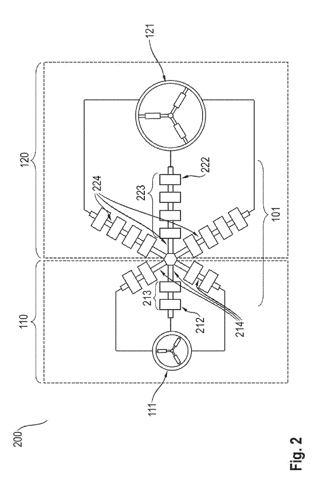
[0034]FIG. 2 shows a schematic illustration 200 of an embodiment of the method according to aspects of the invention with a configuration, changed in respect of the number of energy modules, of the ...


PUM


Abstract

A method for configuring a battery for operation of at least two N-phase electric machines, in which a battery includes a plurality of energy modules, and the energy modules each have at least one energy cell and at least two power switches. A respective N-phase electric machine is assigned a respective group of the plurality of energy modules, and the assignment is carried out in accordance with an estimation of a respective energy consumption of the respective N-phase electric machines on the basis of a respective load of the respective N-phase electric machines which load is to be assumed.

Description

CROSS-REFERENCE TO RELATED APPLICATION[0001]This application claims priority to German Patent Application No. DE 10 2018 106 307.5, filed Mar. 19, 2018, which is incorporated by reference herein in its entirety.FIELD OF THE INVENTION[0002]The present invention relates to a method, to a system# and to a multi-level converter system for an electric vehicle having at least two electric motors which are assigned to a respective drive unit, in which modules of a battery are organized with respect to an assumed energy consumption of the respective electric motors.BACKGROUND OF INVENTION[0003]Modern electrically operated vehicles typically have more than one drive motor. If, for example, in each case, one electric motor is arranged on a front axle and one electric motor is arranged on a rear axle, the respective electric motors have a separate alternating current system. The reason for this are different effects on the front axle and rear axle, for example during cornering or during unstab...

Claims


Application Information

Patent Timeline
Patent Type & Authority Applications(United States)
IPC IPC(8): H02P5/74
CPCB60Y2200/91B60L50/60H02P5/74B60Y2400/60H02P5/46B60L2220/42B60L2220/58H02P27/14Y02T10/64Y02T10/70
Inventor JAENSCH, MALTEKACETL, JANKACETL, TOMASDIBOS, HERMANN HELMUTSPECHT, EDUARDKORTE, CHRISTIANGÖTZ, STEFAN
Owner DR ING H C F PORSCHE AG
Why Eureka
Try Eureka