Suction gripper system for handling at least one article

a gripper system and gripper technology, applied in the direction of manipulators, work holders, conveyor parts, etc., can solve the problems of high force expenditure, limited use in the case of sensitive surfaces, and magnet restricting a degree of mobility, so as to achieve low friction during the centering process and high density

Active Publication Date: 2019-09-26
CARL ZEISS VISION INT GMBH
View PDF5 Cites 4 Cited by
  • Summary
  • Abstract
  • Description
  • Claims
  • Application Information

AI Technical Summary

Benefits of technology

[0021]In an exemplary embodiment, the suction calotte may comprise a suction attachment. In particular, the suction attachment may be configured to adapt to a part of a surface of the article. Furthermore, the suction attachment may be configured to close off the part of the surface of the article air-tightly. In particular, air-tight closing-off of the part of the surface may occur exactly when the suction calotte has had a negative pressure applied thereto. Typically, the suction attachment may in particular be configured to attach to only a part of the surface to prevent the entire article from being sucked in when the negative pressure is applied to the suction calotte.
[0032]In another exemplary embodiment, the suction gripper system may have a parting line, for example a parting point, in particular a natural parting point, which may run between the ball and the magnetic element. The parting line may be used for example as a parting point for a repair or an exchange process, in particular may serve as a parting point for a tool change, such as an exchange of a suction attachment, typically for an exchange of the suction calotte. Here, it is typically possible, by an action of force in the form of a negative pressure (pulling action), for the magnetic force that prevails between the ball and the magnetic element in the rest state to be overcome, and thus for the suction calotte to be separated from the counterpart. The suction calotte can thereupon be cleaned and / or replaced and subsequently reused. Alternatively or in addition, a contaminated and / or damaged suction calotte can be easily and quickly exchanged for another suction calotte. In a further embodiment, a suction calotte in use may be replaced with another suction calotte which may in particular have a deviating form and which can thus better adapt to the form and / or the position of the article to be handled.
[0050]The suction gripper system according to the disclosure, which can also be referred to as “wobble-action suction cup,” the present methods and the use have numerous advantages in relation to conventional devices, methods, and uses. In particular, it is for example possible for an expenditure of force that is applied during a setting-down of the suction gripper system onto the article to be reduced in relation to devices known from the related art. For this reason, it may be possible for the suction gripper system according to the disclosure and the present method, by contrast to conventional devices and methods, to be suitable for handling articles with a relatively sensitive surface. In particular, the suction gripper system according to the disclosure and the proposed methods may for example be distinguished by a lower action of force on the article to be handled than conventional devices and methods. For example, it may be possible that, in the case of the proposed suction gripper system and the methods, a holding force of the magnetic element does not give rise to any friction between counterpart and suction calotte, whereby the force required for handling the article, in particular the force required for positioning, is reduced in relation to conventional devices and methods.
[0052]Furthermore, the suction gripper system proposed here and the proposed methods may exhibit easier handling, in particular a smoother or lower-friction movement, in relation to conventional devices, methods, and uses. In particular, friction forces can be minimized by a punctiform abutment of the ball against the magnetic element. In particular, the suction gripper system proposed here and the methods may exhibit smooth rolling of the ball on the surface of the magnetic element. This may for example be made possible by virtue of the ball, for example similarly to that in a ball bearing, being typically rotationally freely movable and being movable in translation in one direction, in particular in a vertical direction, for example in a z-direction, in the ball receptacle, and being capable of being held for example similarly to being in a cage. In particular, the degree of freedom in a z-direction could in this case for example compensate any occurring system-induced tolerances, for example tolerances that may arise as a result of an occurring deviation of a flat disc with respect to a ball section.
[0054]In particular, the suction gripper system according to the disclosure, the present methods and the proposed use may permit more reliable centering, in particular a more reliable return into the initial state, and thus more reliable handling of the article in relation to devices, methods, and uses known from the related art. For example, lower friction during a centering process may be attained in particular owing to the punctiform abutment of the ball, in particular of the steel ball, against the magnetic element, such as against the magnetic disc. It may in particular be the case that only rolling friction exists between the ball and the magnetic element. In particular, the steel ball may be attracted by magnetic field lines of the magnetic disc. For example, the magnetic field lines may have a high density, in particular the highest density, in the middle of the magnetic disc, in particular in the middle of the respective poles of the magnetic disc. In particular, the ball may for example be attracted with the greatest intensity by the high density of the magnetic field lines in the middle of the magnetic disc. It is consequently possible for the ball, for example the steel ball, owing to the low friction between ball and magnetic element, to be centered in the middle of the magnetic disc by the high density of the magnetic field lines, and it is possible in particular for the suction gripper system to be returned into its initial state in this way. Furthermore, with the suction gripper system according to the disclosure, it can be ensured that the ball, for example a meridian of the ball, is not pushed, for example displaced, beyond a margin of the magnetic element, in particular beyond an edge of the magnetic disc. In this way, it would for example be possible for the ball to be prevented from passing into condensed field lines at the edge of the magnetic disc, for example by the deflection stop.

Problems solved by technology

For example, a high expenditure of force is normally necessary during a setting-down of the suction cup, such that use in the case of articles with a sensitive surface is possible only to a limited extent.
Furthermore, in general, a holding force of a magnet restricts a degree of mobility, for example the mobility between spherical calotte and ball socket.
Furthermore, the devices used in the related art for the resetting are generally, owing to the system, not capable of permitting a complete resetting, in particular a recentering.

Method used


Image

  • Suction gripper system for handling at least one article
  • Suction gripper system for handling at least one article
  • Suction gripper system for handling at least one article

Examples


Embodiment Construction

[0095]Further details and features of the disclosure will become apparent from the following description of preferred exemplary embodiments. The respective features can be realized by themselves or as a plurality in combination with one another. The disclosure is not restricted to the exemplary embodiments. The exemplary embodiments are illustrated schematically in the figures. In this case, identical reference numerals in the individual figures designate identical or functionally identical elements or elements corresponding to one another with regard to their functions.

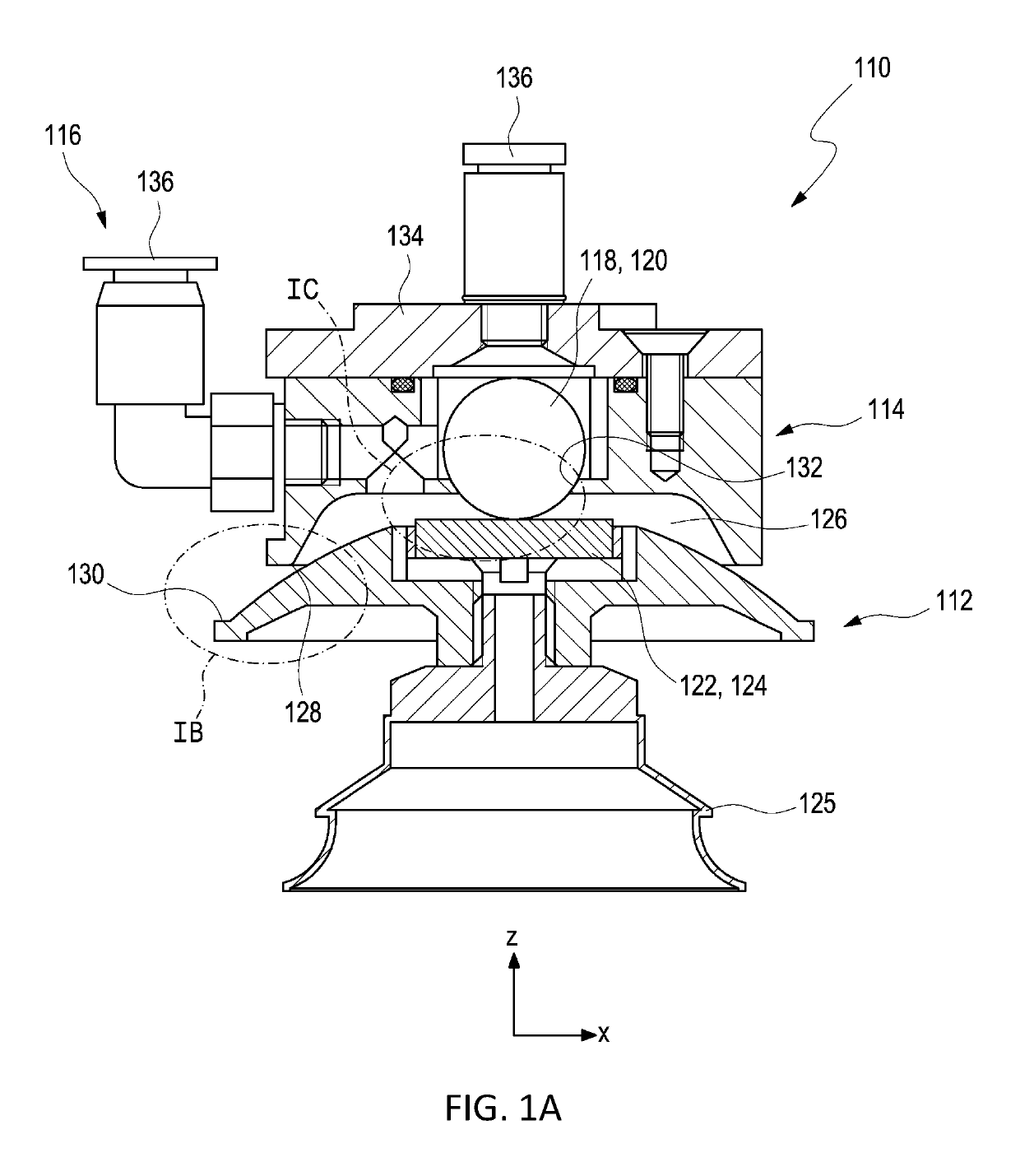
[0096]FIG. 1A shows an exemplary embodiment of a suction gripper system 110 for handling at least one article (not shown) in a sectional illustration. The suction gripper system 110 comprises a suction calotte 112 for the handling of the at least one article with pressure and comprises a counterpart 114 configured correspondingly to the suction calotte 112. In particular for the application of pressure, typically neg...


PUM


Abstract

A suction gripper system includes a suction calotte for the handling of at least one article and a counterpart configured correspondingly to the suction calotte. Further, the suction gripper system includes a magnetic element and a movably mounted ball, which are arranged to interact magnetically with respect to one another to influence a spatial position of the suction calotte in relation to the counterpart. Further, a method for handling the at least one article, a method for producing at least one spectacle lens, and the use of the suction gripper system are disclosed.

Description

CROSS REFERENCE TO RELATED APPLICATIONS[0001]This application claims priority to European patent application EP 18 162 828.0 filed on Mar. 20, 2018, which is hereby incorporated by reference in its entirety.TECHNICAL FIELD[0002]The present disclosure relates to a suction gripper system and to a method for handling at least one article, to a method for producing at least one spectacle lens, and to a use of the suction gripper system. Here, the suction gripper system and the method may be configured in particular for acting with the lowest possible forces and friction on an article to be handled, in particular an optical element, typically spectacle lenses, typically for fixing and receiving the article with the suction gripper system.BACKGROUND[0003]The related art discloses devices for suctioning, lifting, transporting, and relocating workpieces. Such devices and methods have been used for decades in particular in the industrial manufacturing sector.[0004]DE 20 2010 015 939 U1 discl...

Claims


Application Information

Patent Timeline
Patent Type & Authority Applications(United States)
IPC IPC(8): B25J15/06
CPCB25B11/005B25J15/0658B25J15/0683B65G47/91B65G47/92B65G49/06B25J15/0028B25J15/0616
Inventor KURZ, NORBERT
Owner CARL ZEISS VISION INT GMBH
Why Eureka
Try Eureka