Lighting Apparatus

Active Publication Date: 2019-09-26
ARTEMIDE
View PDF6 Cites 3 Cited by
  • Summary
  • Abstract
  • Description
  • Claims
  • Application Information

AI Technical Summary

Benefits of technology

[0007]It is an object of the present invention to provide a lighting apparatus which overcomes the drawbacks of the prior art described herein; in particular, it is an object of the invention to provide a lighting a

Problems solved by technology

However, the known apparatuses may not be fully satisfactory, in par

Method used


Image

  • Lighting Apparatus
  • Lighting Apparatus
  • Lighting Apparatus

Examples


Example

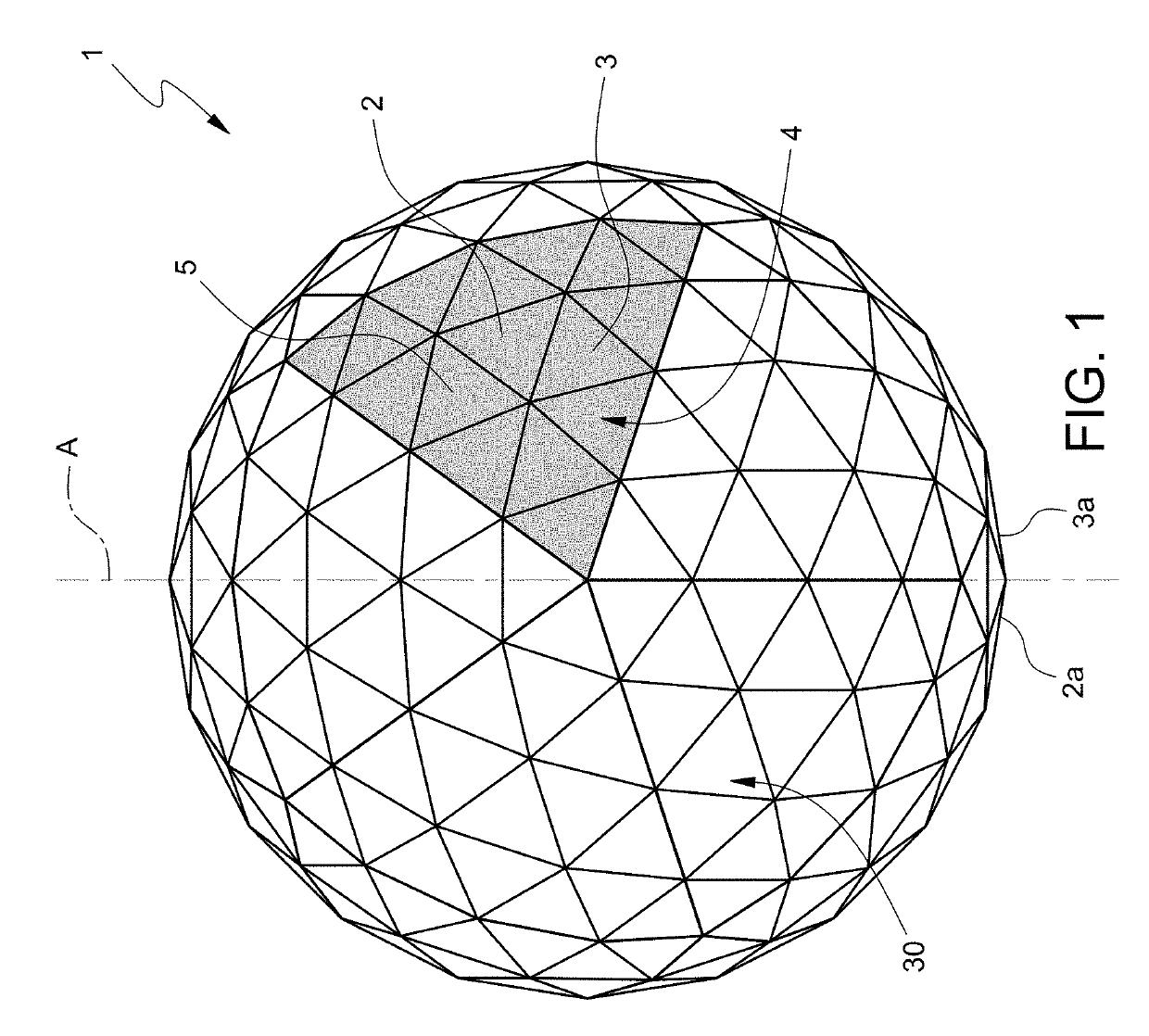
[0019]In FIG. 1, number 1 indicates, as a whole, a lighting apparatus for lighting indoor and / or outdoor environments.

[0020]The apparatus 1 includes a plurality of polyhedral sectors 2 defining respective modules 3 (one of which, for illustrative purposes only, is highlighted in grey, for its identification with respect to the other modules 3).

[0021]In particular, the apparatus 1 extends along a central axis A and the sectors 2, therefore the modules 3, are located about axis A, which constitutes a central symmetry axis of the apparatus 1.

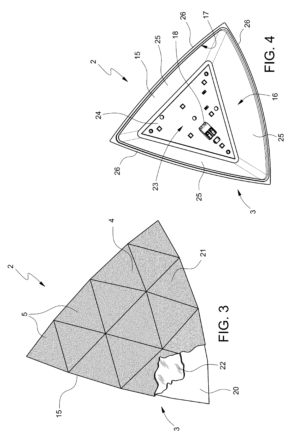
[0022]Each sector 2, i.e. each module 3, has an outer surface 4, which is a polyhedral surface formed by a plurality of polygonally outlined plane faces 5 and defines the light emitting surface of the module 3.

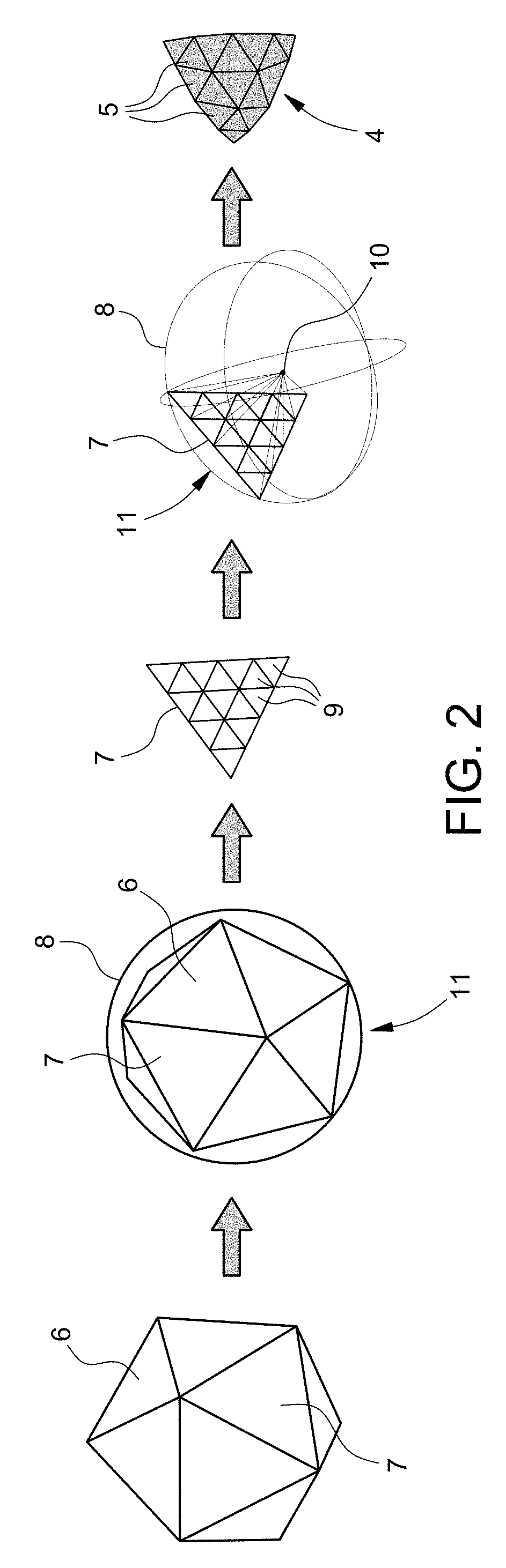
[0023]The shape of the modules 3, i.e. the polyhedral sectors 2, is geometrically defined by the second degree development of a polyhedron on a sphere circumscribing the polyhedron.

[0024]In particular, as schematically shown in FIG. 2, the sh...


PUM


Abstract

A lighting apparatus comprises a plurality of light modules; each module comprises: a hollow body provided with a light box having a light exit opening and housing a LED light source controlled by a control unit; a diffusing screen positioned on the opening to uniform the light passing through the opening; a closure cover, positioned above the diffusing screen; a transparent capacitive film positioned on a face of the closure cover and connected to the control unit to define a touch control device of the module; the modules are shaped as respective polyhedral sectors arranged around the first axis and each module defines an independent light module controlled by the respective touch control device independently of the other modules.

Description

CROSS-REFERENCE TO RELATED APPLICATIONS[0001]This Patent Application claims priority from Italian Patent Application No. 102018000003925 filed on Mar. 26, 2018, the entire disclosure of which is incorporated herein by reference.TECHNICAL FIELD[0002]The present invention relates to a lighting apparatus, in particular for ambient lighting (interior and / or exterior).BACKGROUND ART[0003]In the lighting industry, particularly the interior lighting industry, a large number of different types of lighting apparatuses are known, which can also provide a multiplicity of functions and lighting effects.[0004]A common requirement is to change the luminosity or light intensity.[0005]However, the known apparatuses may not be fully satisfactory, in particular with regard to simplicity and luminosity control efficiency.[0006]On the other hand, in the lighting industry there is a constant search for technical solutions, which also allow them to be integrated into aesthetically original objects and fu...

Claims


Application Information

Patent Timeline
IPC IPC(8): F21V23/04F21S10/00F21V3/02
CPCF21V3/02F21Y2115/10F21S10/00F21V23/0485F21S2/005F21V3/06F21Y2107/40
Inventor FRANZOSI, ROBERTO EFREMGALLUCCI, ANDREA
Owner ARTEMIDE
Why Eureka
Try Eureka